Dummy or Idle Coils
These are used with wave-winding and are resorted to when the requirements of the winding are not met by the standard armature punchings available in armature-winding shops. These dummy coils do not influence the electrical characteristics of the winding because they are not connected to the commutator. They are exactly similar to the other coils except that their ends are cut short and taped. They are there simply to provide mechanical balance for the armature be- cause an armature having some slots without windings would be out of balance mechanically. For example, suppose number of armature slots is 15, each containing 4 sides and the number of poles is 4. For a simplex wave-windings,
which does not come out to be an integer (Art. 26.28) as required by this winding. However, if we
This makes the winding possible.
Uses of Lap and Wave Windings
The advantage of the wave winding is that, for a given number of poles and armature conductors, it gives more e.m.f. than the lap winding. Conversely, for the same e.m.f., lap winding would require large number of conductors which will result in higher winding cost and less efficient utilization of space in the armature slots. Hence, wave winding is suitable for small generators especially those meant for 500-600 V circuits.
Another advantage is that in wave winding, equalizing connections are not necessary whereas in a lap winding they definitely are. It is so because each of the two paths contains conductors lying under all the poles whereas in lap-wound armatures, each of the P parallel paths contains conductors which lie under one pair of poles. Any inequality of pole fluxes affects two paths equally, hence their induced e.m.fs. are equal. In lap-wound armatures, unequal voltages are produced which set up a circulating current that produces sparking at brushes.
However, when large currents are required, it is necessary to use lap winding, because it gives more parallel paths.
Types of Generators
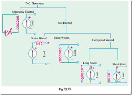
Generators are usually classified according to the way in which their fields are excited. Genera- tors may be divided into (a) separately-excited generators and (b) self-excited generators.
(a) Separately-excited generators are those whose field magnets are energised from an independent external source of d.c. current. It is shown diagramatically in Fig. 26.41.
(b) Self-excited generators are those whose field magnets are energised by the current produced by the generators themselves. Due to residual magnetism, there is always present some flux in the poles. When the armature is rotated, some e.m.f. and hence some induced current is produced which is partly or fully passed through the field coils thereby strengthening the residual pole flux.
There are three types of self-excited generators named according to the manner in which their field coils (or windings) are connected to the armature.
(i) Shunt wound
The field windings are connected across or in parallel with the armature conductors and have the full voltage of the generator applied across them (Fig. 26.42).
(ii) Series Wound
(b) respectively. In a compound generator, the shunt field is stronger than the series field. When series field aids the shunt field, generator is said to be commutatively-compounded. On the other hand if series field opposes the shunt field, the generator is said to be differentially compounded. Various types of d.c. generators have been shown separately in Fig. 26.45.
Brush Contact Drop
It is the voltage drop over the brush contact resistance when current passes from commutator segments to brushes and finally to the external load. Its value depends on the amount of current and the value of contact resistance. This drop is usually small and includes brushes of both polarities. However, in practice, the brush contact drop is assumed to have following constant values for all loads.
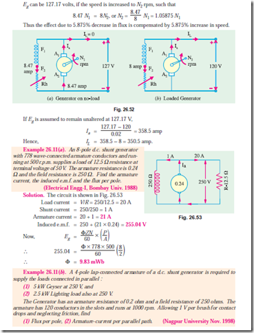
Example 26.10. A d.c. shunt generator has an induced voltage on open-circuit of 127 volts. When the machine is on load, the terminal voltage is 120 volts. Find the load current if the field- circuit resistance is 15 ohms and the armature-resistance is 0.02 ohm. Ignore armature reaction.
(Madras University April 1997, Bharathiar University Nov. 1997)
Solution.
Note : Even though the question does not specify some conditions, the solution given here is based on correct approach to deal with the case.
Generator on no load :
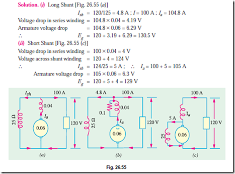
Example 26.14. In a 120 V compound generator, the resistances of the armature, shunt and series windings are 0.06 W, 25 W and 0.04 W respectively. The load current is 100 A at 120 V. Find the induced e.m.f. and the armature current when the machine is connected as (i) long-shunt and as (ii) short-shunt. How will the ampere-turns of the series field be changed in (i) if a diverter of 0.1 ohm be connected in parallel with the series winding ? Neglect brush contact drop and ignore armature reaction.
When a diverter of 0.1 W is connected in parallel with the series winding, the diagram becomes as shown in Fig. 26.55 (b). As per current-divider rule, the current through the series winding is = 104.8 ´ 0.1/(0.1 + 0.04) = 74.86 A. It means that the series field current has decreased from an original value of 104.8 A to 74.86 A. Since No. of turns in the series winding remains the same, the change in series field ampere-turns would be the same as the change in the field current. Hence, the percentage decrease in the series field ampere-turns = (74.86 – 104.8) ´ 100/104.8 = -28.6%.
Note : In case of long shunt connection, the generator has to develop the e.m.f. with shunt field current slightly reduced, compared to the case of short shunt connection. However, the series field winding carries a slightly higher current in latter case. Still, in practice, slight speed adjustment (or shunt field rheostatic variation) may be required to get this e.m.f., as per calculations done above.


