Direct-Current Motor Control
Direct-current controllers are classified as many different types, but essentially they are either manually or automatically operated.
DC CONTROLLERS
Small de motors of, say, less than V2 hp consume very little current upon starting and therefore can be started by placing full voltage across the motor terminals. On the other hand, large de motors cause large initial currents to flow because they have a low resistance, and the excessive current flow during starting may damage the motor or trip the overcur rent device.
To start a large de motor, it is necessary to place a resistance unit in series with the motor so that the starting current is reduced to a safe value. As the motor accelerates, this resistance can be gradually decreased. Once the motor reaches the desired speed, the resistance is no longer necessary because the motor is now generating a voltage which is in opposition to the impressed voltage, thereby preventing excessive cur rent flow. This opposing voltage is called the counterelectromotive force (CEMF), and its value will depend on the speed of the motor, which is greatest at full speed and zero at standstill.
In general, de motors of less than 2-hp rating can be started across the line, but with larger motors it is usually necessary to put resistance in series with the armature when it is connected to the line, as discussed previously. This resistance, which reduces the initial starting current to a point where the motor can commutate successfully, is shorted out in steps as the motor comes up to speed and the countervoltage generated is sufficient to limit the current peaks to a suitable value. Accelerating con tactors that short out successive steps of starting resistance may be con trolled by countervoltage or by definite-time relays.
For small motors used on auxiliary devices the CEMF starter is satisfactory. The definite-time starter is more widely used, however, and has the advantage of being independent of load conditions.
The following diagrams illustrate some of the circuits commonly used for de motor control.
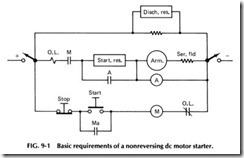
Basic requirements of a nonreversing de starter in its simplest form is shown in Fig. 9-1. When the start push button is depressed, line contac tor M closes, energizing the motor armature through the starting resis tance. As the motor comes up to speed, the countervoltage, and the voltage across the motor armature and series field, increases. At a pre determined value the accelerating contactor A closes, shorting out the starting resistance.
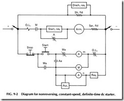
Figure 9-2 shows a typical nonreversing, constant-speed, definite time starter. The accelerating contactor is equipped with a time delay mechanism. This contactor A is of the magnetic-flux-decay type. It is spring-closed, equipped with two coils, and has a magnetic circuit that re tains enough magnetism to hold the contactor armature closed and the contact open indefinitely. Main coil Am has sufficient pull to pick up the armature and produce permanent magnetization. Neutralizing coil An is connected for polarity opposite the main coil. It is not strong enough to affect the pickup or holding ability of the main coil, but when the latter is deenergized, the neutralizing coil will buck the residual magnetism so
that the contactor armature is released by the spring, and the contacts close. By adjusting the potentiometer, the voltage impressed on this coil and hence the time required for the contactor to drop out can be varied. When the start button is depressed, accelerating contactor coil Am is energized, causing contact A to open and auxiliary contact Aa to close. Contact Aa energizes line contactor M, and normally open auxiliary con tacts Ma establish a holding circuit. Neutralizing coil An is also ener gized. Opening of contact Ma deenergizes coil Am, and contactor A starts timing. At the set time the main normally closed contacts on A close, shorting out the starting resistance and putting the motor across the line.
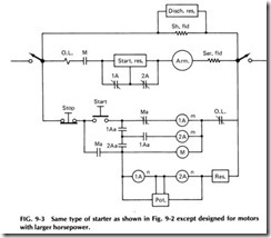
The same kind of a starter as in Fig. 9-2 but designed for use with a motor of larger horsepower is shown in Fig. 9-3. This starter provides two steps of definite-time starting. The operation is essentially the same as in Fig. 9-2, but the first accelerating contactor lA does not short out all the starting resistance. It also starts 2A timing, which finally shorts out the remaining resistance. The normally open auxiliary contacts on the accel erating contactors in Figs. 9-2 and 9-3 are arranged so that it is necessary for the accelerators to pick up before the line contactor can be energized. This is a safety interlocking scheme that prevents starting the motor across the line if the accelerating contactors are not functioning properly.
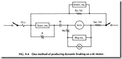
One way of producing dynamic braking is shown in Fig. 9-4. Control circuits have been omitted, since they are a duplicate of those shown in
Figs. 9-2 and 9-3. Line contactor M has two poles, one normally open and the other normally closed. Both poles are equipped with an operating coil and are on the same armature, which is hinged between the contacts. In starting, when line contactor M closes, normally closed contact Ma opens. When the stop button is depressed, the line contactor drops out,
and contact Ma closes. The motor, now acting as a generator, is con nected to the braking resistor, and coil Ma is energized by the resultant voltage. It causes M to seal in tightly, establishing good contact pressure and preventing this contact from bouncing open.
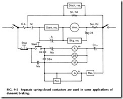
In the more modern types of controllers a separate spring-closed contactor is used for dynamic braking. See Fig. 9-5. Operation is similar to that described for Fig. 9-2, except that the energizing of coil Am and the picking up of accelerating contactor A, closing contact Aa, energize dynamic braking contactor DB, which in turn energizes line contactor M through its auxiliary contact DBa. This arrangement not only ensures that the dynamic braking contactor is open but also that it is open before the line contactor can close. To obtain accurate inching, such as is re quired for most machine tool drives, the motor must respond instantly to the operation of the push button. In the scheme shown in Fig. 9-5, the closing of the line contactor is delayed until the accelerating contactor and the dynamic braking contactor pick up.
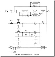
Figure 9-6 shows an arrangement to secure quicker response of the motor for more accurate inching. Accelerating contactors lA and 2A are energized in the off position. Hence, when the start button is depressed, the dynamic braking contactor picks up immediately, and its auxiliary contact DB a picks up M line contactor.
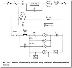
One method of connecting the full-field relay, used with adjustable speed motors having a speed range in excess of 2 to 1, is shown in Fig. 9-7. Coil FF is energized by the closing of the normally open auxiliary contact Aa and remains closed until the last accelerating contactor drops out. Contacts of the full-field relay FF are connected to short out the field rheostat, thereby applying maximum field strength to the motor during the starting period.
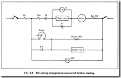
Another method of applying the full-field relay is shown in Fig. 9-8. This arrangement ensures full field on starting and provides for limiting the armature current when the motor is accelerating from the full-field speed to the speed set by the rheostat. Field accelerating relay FA is equipped with two coils, one a voltage coil connected across the starting resistance and the other a current coil connected in series with the motor armature. See Fig. 9-2 for the remainder of the circuit. Wben line contactor M closes, the voltage drop across the starting resistor is practically line voltage, and relay FA is picked up quickly. When accelerating con tactor A closes, voltage coil FAv is shorted, but the closing of A produces a second current peak, and current coil FAc holds relay FA closed. As the motor approaches full-field speed, this current decays and allows the FA contacts to open, weakening the motor field. When the motor attempts to accelerate, the line current again increases. If it exceeds the pickup value of coil FAc, the relay will close its contacts, arresting acceleration and causing a decay of line current, which again causes FA to drop out. High inductance of the motor field plus inertia of the motor and drive prevent rapid changes in speed. Hence the motor will not reduce its speed, but the increased field current will reduce the armature current and cause FA to drop out. The fluttering action will continue until the motor reaches the speed set by the r eostat. Setting of the FA relay current coil determines the maximum current draw during this part of the acceleration period. Since relay FA must handle the highly inductive field circuit, a good blowout arrangement is necessary. Hence the relay is usually equipped with a shunt blowout coil, FABO.
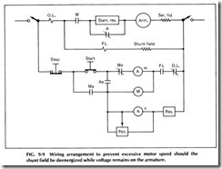
Connections of field lost relay, to prevent excessive speed if the shunt field is deenergized while voltage remains on the armature, is shown in Fig. 9-9. It usually consists of a current relay in series with the motor shunt field and is adjusted to pick up on full-field current and re main closed at any current within the operating range of the motor field current. Contacts of relay FL are connected in series with the overload relay contacts so that the opening of its contacts will deenergize the con trol by opening the line contactor. rrhis type of field loss protection does not protect against the possibility of a short circuit across a part of the field, say across the one field coil. This would cause the motor speed to rise considerably, but the current in the field circuit would also rise. Con sequently, the series current relay would not respond.
