The OR Gate
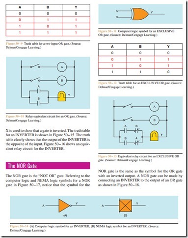
The computer logic symbol and the NEMA logic symbol for the OR gate are shown in Figure 50 – 8. The OR gate has a high output when either or both of its inputs are high. Refer to the truth table shown in Figure 50 – 9. An easy way to remember how an OR gate functions is to say that any one input = a one output. An equivalent relay circuit for the OR gate is shown in Figure 50 – 10. Notice in this circuit that if either or both of the relays are energized, there will be an output at Y.
Another gate that is very similar to the OR gate is known as an EXCLUSIVE OR gate. The symbol for an EXCLUSIVE OR gate is shown in Figure 50 – 11. The EXCLUSIVE OR gate has a high output when either, but not both, of its inputs are high. Refer to the truth table shown in Figure 50 – 12. An equivalent relay circuit for the EXCLUSIVE OR gate is shown in Figure 50 – 13. Notice that if both relays are energized or de-energized at the same time, there is no output.
The INVERTER
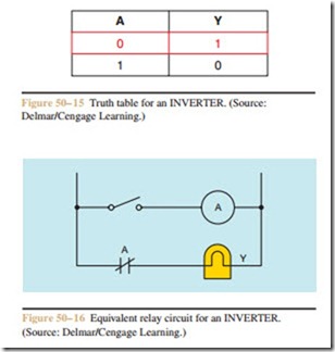
The simplest of all the gates is the INVERTER. The IN- VERTER has one input and one output. As its name implies, the output is inverted, or the opposite of the input. For example, if the input is high, the output is low, or if the input is low, the output is high. Figure 50 – 14 shows the computer logic and NEMA symbols for an INVERTER.
In computer logic, a circle drawn on a gate means to invert. Since the “O” appears on the output end of the gate, it means the output is inverted. In NEMA logic an
The truth table shown in Figure 50–19 shows that the output of a NOR gate is zero, or low. when any input is high. Therefore, it could be said that any one input a zero output for the NOR gate. An equivalent relay circuit for the NOR gate is shown in Figure 50–20.
Notice in Figure 50–20 that if either relay A or B is energized, there is no output at Y.


