Instruments for in-depth testing and scheduled maintenance include
![]() Polarization index test
Polarization index test ![]() Step voltage test
Step voltage test
![]() Power quality test instruments
Power quality test instruments
FIGURE 8.8 A stethoscope used to pinpoint problems. SKF USA Inc.
Surge Tester
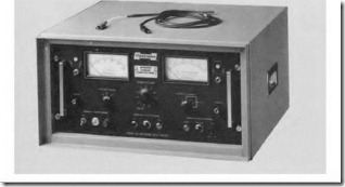
The surge tester (Fig. 8.9) has the capability of detecting a turn-to-turn fault in individual coils before it becomes an actual breakdown. It can also compare two identical circuits during this test. Other test instruments can compare identical circuits as well, but can’t check the turn-to-turn insulation. EASA estimates that 80 percent of insulation breakdowns start as a turn-to-turn fault.
During the test procedure, this instrument also performs a low-resistance test that (in rare cases) will reveal problems that the surge comparison test
FIGURE 8.9 A surge tester capable of comparison and turn-to-turn voltage stress testing. Electrom Instruments.
misses. One example is a poor connection in a multiple-circuit winding. The faulty connection wasn’t revealed because the surge test is based on inductance. (When one wire of a multiple wire, winding conductor [for example, when four #12 wires are used instead of one #6] is open, the inductance can be the same, but the resistance is less.)
The surge tester uses up to 10 amperes in its resistance test. The results are printed in hard copy for further review.
The surge tester is often used in predictive maintenance programs. The test unit can be applied at the motor’s disconnect, where it will test both the motor and its supply lines. It’s not always used during the initial test procedure because of its weight. It is often used to confirm problems that are hard to identify (before a motor is replaced).
The surge tester uses a precisely controlled spike of voltage on the windings. The duration of the spike is so short that it doesn’t damage the insulation. The power of the instrument is so well controlled that an arc won’t cause carbon tracking, unless the test isn’t stopped soon enough.
When a high voltage is impressed turn to turn, any weak spot in the insulation will arc. The test should be stopped as soon as a fault is detected, to prevent further damage. A serious problem has been identified, and the motor can be operated until it’s convenient to replace it. There are numerous cases where this tester has saved thousands of dollars in lost production.
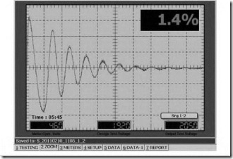
Comparison-testing is done with the surge tester’s dual-trace (signal) oscilloscope (Fig. 8.10). Thro identical windings are tested at the same time. Each signal records the inductance of its respective winding. Any difference in inductance will separate the two signals, indicating a problem. If the signal scrambles, the test is stopped immediately. A scrambled signal indicates arcing caused by a weak spot in the insulation. If the weak spot is visible, it can sometimes be repaired.
Different-shaped signals identify problems such as a turn-to-turn short ![]() phase-to-phase short, wrong connection (internally or externally), and grounded turns.
phase-to-phase short, wrong connection (internally or externally), and grounded turns.
Rotor Test
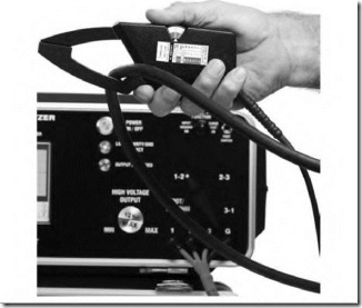
With the Electrom rotor bar clamp, (Fig. 8.11) a motor’s rotor can be tested in place. Open rotor bars described in Chapter 6 can be detected without disassembling the motor.
FIGURE 8.10 The signal on the surge tester’s dual-trace oscilloscope shows that the two windings being tested have no problem. The motor is being tested from its disconnect. Electrom Instruments.
FIGURE 8.11 Rotor clamp being used to test for rotor problems while the motor is nmning. Electrom Instruments.
DC armatures can be tested using a special attachment shown in Fig.
8.12. Large armatures can also be tested, as well as those with equalizer connections.
Polarization Index Test with a Megohmmeter
The polarization index test is done to determine the condition of the insulation that protects the coils. Insulation being tested is located between the coil wire and any path to the frame. (This includes air over the end turns of the coils.) The test is dependable for only form-wound or taped coils that have no wire exposed to air (such as random-wound motors). The randomwound coils are seldom taped and sealed, making the test easily corrupted by changing conditions such as high humidity or conducting dirt.
FIGURE 8.12 Adapter used to test armature windings with a surge tester. Electrom Instruments.
In the polarization index test described below, it is assumed that the motor’s insulation is not made of epoxy resin or one of the many polymer products. The test doesn’t work on these materials.
Many industries don’t use this test because it’s hard to identify the insulation varieties that invalidate the test. The majority of motors in service are random wound and, as explained above, can’t be reliably tested due to the many corrupting variables.
The polarization index test is a trending procedure that documents the degradation of insulation over a timed series of tests. The tests are done at 6to 12-month intervals. A reading is taken at I minute and again at 10 minutes from the time the voltage is applied. The 10-minute reading is divided by the I-minute reading to get the polarization index. The result should be between 2 and 5. A reading below 2 indicates conducting dirt or moisture. If the result is above 5, the insulation is crystallized (brittle) and could fail.
During the test, the molecules in the insulation are becoming aligned. Current flows and resistance is lower during the alignment of the molecules ![]() and decreases to a lesser value at 10 minutes. The 10-minute value has higher resistance than the 1-minute value.
and decreases to a lesser value at 10 minutes. The 10-minute value has higher resistance than the 1-minute value.
The motor has to be offline for at least an hour before the polarization index test is performed. Energizing the winding with any type of voltage source will align the free molecules and cause an invalid test. It is good practice to ground the motor leads to the frame for an hour before testing.
As insulation ages, it becomes brittle (crystallized) and there are fewer free molecules. This is why it takes less time to align the free molecules. The test result number becomes higher as the aging progress goes on. At some age, the time it takes to polarize the insulation gives a result greater than 5. At this time the insulation is so brittle that cracks form. If there are conducting contaminants present, the current flows, carbon forms, and there is complete insulation breakdown.
Step Voltage Test
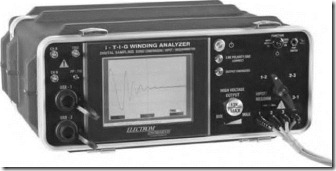
The step voltage test is done with an instrument called a winding analyzer (Fig. 8.13a). The machine is computer-compatible and can give a printout of the test results. The printouts show the voltage and current of each step (Fig. 8.13b).
FIGURE 8.13 (a) The winding analyzer used in the step voltage test. Electrom Instruments.
FIGURE 8.13 (continued) (b) Printouts of the step voltage test. Electrom Instruments.
The test measures the current leakage (caused by contaminants) from the motor’s winding to its frame. It is a trending procedure similar to the polarization index test. However, unlike the polarization index test, it works on any type of insulation. It’s much more precise than a megohmmeter and can store information for future comparison.
The test can be done at the control terminals or at the motor’s junction box. (Control components that can be damaged should be isolated from the test.) Voltage should be raised slowly to its test value to avoid damaging spikes. The leads should be grounded to the frame after the test is completed.
The test procedure is as follows: DC voltage is applied in steps, starting with 500 volts, then 1000 volts, etc., up to the motor’s high-potential test value: 2 x rated voltage + 1000 volts.
Each voltage value is applied for 1 minute. The machine then records the voltage and current of each step. There is an inrush of current when the voltage is applied. This current charges the capacitor effect of the winding and polarizes the insulation. (After I minute, the current stabilizes to its leakage value.) Leakage current rises as the voltage increases. A sharp increase over the previous test indicates the winding should be cleaned.
High-Potential Test
The high-potential (hi-pot) test is done to stress the phase-to-ground (slot) insulation. Always use an ohmmeter before using the hi-pot test (Fig. 8.14). The windings should read at least 50 megohms to the frame before using the hi-pot. Dirty or wet windings should be cleaned and dried before the hi-pot test. If DC voltage is used, it should be 1.4 times the AC values.
Accepted AC test voltage for high-potential testing is as follows:
• New windings: 2 x rated voltage + 1000 volts for 1 minute
• Small motors rated 250 volts or less: 1000 volts for I minute
These variations of the above limits are permissible:
• An equivalent test is 1.2 times the above voltages for I second.
• The above voltages x 1.6 for 1 minute (if DC voltage is used).
• Old or contaminated windings: 60 percent of the above voltages for the same time.
FIGURE 8.14 A high-potential (hi-pot) test instrument. Hipotronics, Inc.
 AC should never be used on motors over 150 horsepower. Always ground the motor leads to the motor frame after each test to discharge voltage stored by the capacitance of the unit. The hi-pot test can be destructive to the insulation. The test instrument should have an automatic trip feature that shuts it off before damage occurs.
Hermetically sealed refrigeration compressor motors have been damaged when windings were tested while under a vacuum. There are theories as to why this happens, but nothing credible. The best advice is: Don’t hi-pot sealed compressor motors.

![clip_image003[4] clip_image003[4]](http://machineryequipmentonline.com/electric-equipment/wp-content/uploads/2017/05/clip_image0034_thumb.jpg)
![clip_image007[5] clip_image007[5]](http://machineryequipmentonline.com/electric-equipment/wp-content/uploads/2017/05/clip_image0075_thumb.jpg)
![clip_image010[4] clip_image010[4]](http://machineryequipmentonline.com/electric-equipment/wp-content/uploads/2017/05/clip_image0104_thumb.jpg)
![clip_image012[5] clip_image012[5]](http://machineryequipmentonline.com/electric-equipment/wp-content/uploads/2017/05/clip_image0125_thumb.jpg)
