Reading and understanding ladder logic
Once the hardwire relay logic concepts are understood then its easy to comprehend ladder logic.
The term ‘Programmable Logic Controllers’ (PLCs) originated from relay-based control systems.
In a PLC, there is full flexibility to change the sequence of operations and interlocks for different conditions.
There are integrated circuits and internal logic in the PLC, in place of discrete relays, coils, timers, counters, and other such devices.
PLCs provide greater computational capabilities and accuracy, to achieve increased flexibility and reliability, than hard-wired relays.
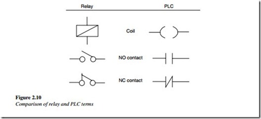
The symbols and control concepts used in PLCs come from relay-based control and form the basis of ladder logic programing (Figure 2.10).
In the following sections, commonly used terminology for ladder logic is dealt with. The terminology used in commercially available PLCs from various manufacturers may differ slightly but the concepts remain the same.
PLC terminology
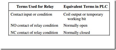
PLC terminology may differ from relay terminology, but the control concepts are the same.
working bit NO contact of relay condition Normally open NC contact of relay condition Normally closed As such, there is no equivalence between these terms. The term ‘condition’ is only used to describe ladder logic diagram programs in general and is equivalent to a set of basic instructions. The terms input/output are used for reference to I/O bits assigned to input and output signals.
In ladder logic programing, the following two types of instructions are used:
1. Instructions that correspond to the conditions of the ladder logic diagram.
They are used in instruction form only when converting a program to mnemonic code.
2. Instructions that are used on the right-hand side of the ladder logic diagram are executed according to the conditions on the instruction lines preceding them.
Most of the instructions have at least one or more operands.
Ladder logic diagram
A ladder logic diagram is so-called because the relay logic runs in parallel lines between two power lines and the whole diagram resembles a ladder.
This diagram consists of one vertical line running down the left side, with the horizontal lines branching off to the right. The line on the left is called the bus bar, while horizontal lines are instruction lines or rungs. Along the instruction lines conditions are placed, that lead to other instructions on the right side. Power flow is always from left to right.
Therefore, the logical combination of these conditions from left to right side determines when and how the instructions at the right side are executed.
In a ladder logic diagram, instruction lines can have multiple branches. The vertical pairs of lines are called conditions. Conditions without diagonal lines through them are called NO conditions that correspond to AND, LOAD, or OR instruction.
The conditions with diagonal lines through them are called NC conditions that correspond to AND NOT, LOAD NOT, or OR NOT instruction.
Each condition has a number above/below each condition that indicates the operand bit for the instruction. Operand bit (Input/ Temporary bit) is associated with that condition.
The status of the bit determines the execution condition for the following instructions.
Basic terms used in ladder logic
Normally open and normally closed conditions
Each condition in a ladder logic diagram is either ‘ON’ or ‘OFF’ depending on the status of the operand bit that has been assigned to it. A NO condition is ‘ON’ if the operand bit is ‘ON’ and it is ‘OFF’ when the operand bit is ‘OFF’. On the other hand, a NC condition is ‘ON’ if the operand bit is ‘OFF’ and it is ‘OFF’ when the operand bit is ‘ON’.
In short, an NO condition simply follows the bit status (on => on and off => off) and an NC condition follows inverted bit status (on => off and off => on).
Execution conditions
In a ladder logic program, the logical combination of ‘ON’ and ‘OFF’ conditions before an instruction determines the conditions under which the instruction is executed. This condition is called the execution condition for the instruction. Except for the ‘LOAD’ instruction, all other instructions have execution conditions.
Operands
The operands designated for any of the ladder logic instructions can be I/O bits, flags, work bits or flags, timers, or counters, etc. In a ladder logic diagram, these conditions can be determined using these operands.
Logic blocks
The manner in which the conditions correspond to instructions is determined by the relationship between the conditions, within the instruction lines that connect them. Any group of conditions that go together to create a logic result is called a logic block.
Ladder logic instructions
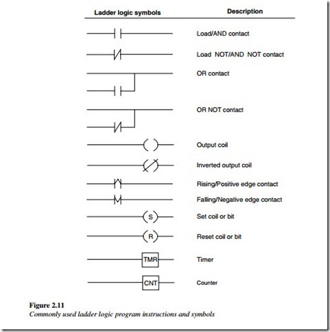
The ladder logic instructions correspond to the conditions on the ladder logic diagram. Ladder instructions are either independent, or are in combination with the logic block instructions, from the execution conditions, based on which the execution of all other instructions are dependent. The most common ladder logic program instructions and the symbols used are shown in the Figure 2.11.
The last instruction required to complete a ladder logic program is the ‘END’ instruction. When the PLC CPU cycle runs through the program, it executes all the instructions up to the first ‘END’ instruction. After the ‘END’ instruction, it returns to the beginning of the program and begins the execution again. Usually, the ‘END’ instruction is the last instruction in the ladder logic program, but it can be placed at any point in the program, like when program debugging is undertaken. No instruction after the ‘END’ instruction is executed. The ‘END’ instruction requires no operands, and no conditions can be placed with the ‘END’ instruction.
Examples of simple ladder logic instructions
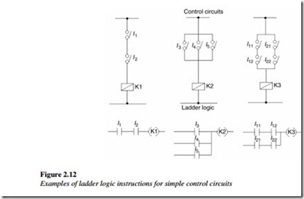
Examples of ladder logic instructions for simple control circuits (AND, OR, AND with OR) are shown in Figure 2.12.
The ladder logic diagram
The ladder logic diagram is one of the methods of programing PLCs and is covered in detail in the IEC standard 61131 Part 3. Ladder diagram is a very convenient way of representing interlocking logics which used to be configured using hard wired devices. Current generation PLCs have other capabilities including that of PID controllers. The IEC standard therefore provides more advanced methods of programing such as Structured Text, Function Block diagram and Sequential Function chart for tasks which cannot be adequately represented using Ladder diagrams alone.


