Reading and understanding electrical drawings
Electrical drawings can represent anything from a single-line power distribution, to a power or control circuit, and are prepared using various symbols for electrical devices and their interconnections with lines representing conductors or wires used for interconnections.
To read and understand electrical drawings, it is necessary to know the following:
• Symbols used for representing electrical devices
• Their interconnections, legends, terminology, and abbreviations
• Sheet numbering and column format for each sheet
• Wire and terminal numbering (an important aspect in understanding electrical drawings).
Wire and terminal numbers are quite useful during installation and termination of cables, and during fault finding and troubleshooting.
It is easy to trace the connections and continuity of wires, if the wires and terminals are numbered using thorough cross-referencing terminology. Various examples of electrical schematics are shown in this section to explain the drawing methodology in practical circuits and in the interest of simplifying the scheme the following have not been included. These are however a MUST and will be insisted upon by the regulatory agencies.
• Any power circuit has to be provided with an isolating mechanism which usually includes the fuses also in the form of a switch-fuse unit. The schematics here depict only the fuse.
An emergency switch or a push button has to be provided near a mechanism to positively isolate the electrical circuit feeding the mechanism in the case of any emergency/accident. The NC contact of such a push button is connected in series with the other control contracts such as overload relay. The push button mechanisms are lockable and need a key to release once the push button is pressed.
Things to look for in an electrical drawing
1. The symbols shown for a device in a circuit represent its de-energized state when no power is applied. It is either a timer NO/NC contact or a relay NO/NC contact in a circuit. In addition, power devices such as circuit breakers and contactors are provided with NO and NC auxiliary contacts which are used for indicating the status of the device in signaling and interlocking circuits.
2. An electrical drawing has a sheet number and each sheet is divided into columns listed vertically as A, B, C, D and horizontally as 1, 2, 3, 4. This kind of matrix arrangement helps in quickly locating a particular device or contact in a sheet. Similarly, it is used to cross-reference a contact.
3. In order to identify different coils and their contacts a letter such as K1, K2 or C1, C2 is placed next to the circle of the coil. Contacts of the same contactor coil are shown with the same letter in the drawing.
4. Particular relay contacts may be used in different circuits at different locations. To give the reader an exact idea of where it is used, a drawing mentions a cross-reference number for each contact showing the sheet number and its matrix number.
5. In general, a heavy line is used to show high current-carrying conductors (mains supply lines, motor connection leads). In contrast, light-looking lines are used to represent low current-carrying conductors (control circuit lines).
6. Control circuit power lines are shown as L1 and L2; load (coils of relay) is connected between these two lines in series with switches, fuses, etc.
7. Conductors intersecting each other with no electrical junction in between are represented with an intersection without any dot. Conversely, conductors having an electrical junction are represented with a dot at the intersection.
8. A broken line in an electrical circuit represents mechanical action. Generally, it is associated with a push button or switch closing or opening a contact.
Sometimes these lines can also indicate in combination with suitable additional symbols, a mechanical interlocking between two or more devices such as contactors or circuit breakers.
9. Dotted lines are used to differentiate an enclosure from field devices.
10. A wiring diagram of electric equipment represents the physical location of the various devices and their interconnections.
11. In an electrical drawing, conductors are marked with cross lines and dimensions of conductors are given alongside. This is used to represent the conductor size of a particular section in a drawing.
Based on the above hints, let us consider a few common examples of electrical drawings.
Example 2.2
Three-phase motor with DOL starter
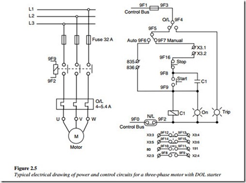
This is depicted in an electrical drawing in Figure 2.5 along with the power and control circuits.
The power circuit consists of a three-phase main supply with a fuse unit for protection purposes. The other side of the fuse unit is connected to a power contactor. The output terminals of the contactor are connected to an overload relay. Finally, the overload relay output terminals are connected to motor terminals.
The control circuit for the motor works on a 110 V AC single-phase supply. The phase of the control supply is connected to a NC contact of the overload relay (O/L).
The wire from the O/L relay contact is connected to an auto/manual mode selector switch.
In the auto mode, the motor gets a start/run command through a potential-free contact (Terminals 835–836) of a relay, which in turn is energized with a Programmable Logic Controller (PLC) output.
In the manual mode, the motor can be started with the help of a start pushbutton. When the start pushbutton is pressed, the control circuit is completed and the auxiliary control contactor (C1) coil is energized. A potential-free NO contact of the contactor (C1) is closed and keeps the contactor C1 latched when the start pushbutton is released. When the auxiliary contactor (C1) is on, the motor power circuit is completed and the motor starts and remains on until the contactor C1 is de-energized and the power circuit to the motor terminals is broken.
For the manual mode, additional interlocks to trip the motor are connected between terminals X3.1 and X3.2. The motor can be stopped with a stop pushbutton. The NC contact of a stop pushbutton breaks the control supply to the auxiliary control contactor (C1) and the motor is stopped. The neutral for the control circuit is connected with a neutral link (N/L).
To indicate that the motor is ON or running, an indication lamp is connected in parallel to the contactor, which goes ON whenever the auxiliary contactor is turned on.
Another indication lamp to indicate a motor trip is connected to a NO contact of the overload relay. When the motor is overloaded, the NO contact is closed and the TRIP indication lamp is turned ON, until the overload relay is reset.
In the control circuit, potential-free contacts, 2 NO and 2 NC, of the auxiliary contactor (C1) are connected to various pairs of terminals such as X3:3 – X3:4 (NC), X3:5 – X3:6 (NC), 80 – 191 (NO), and X2:3 – X2:4 (NO).
The NO contact of the auxiliary control contactor is terminated at the terminals X2:3 and X2:4, and is used in parallel to the start pushbutton NO contact for latching purposes.
In addition, the contact letters 9F8-9F9 are mentioned. This shows the location of the contact in the drawing.
Example 2.3
Three-phase motor with star–delta starter
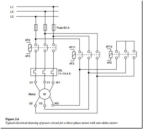
The electrical drawing in Figure 2.6 depicts this power circuit.
The power circuit consists of a three-phase mains supply with a fuse unit, three contactors – line contactor, star contactor, and delta contactor. The line contactor gets its three-phase power supply from the fuse unit and the output terminals of the line contactor are connected to the overload relay.
Overload relay output terminals are connected to the motor terminals – U1, V1, W1. Motor terminals U2, V2, W2 are connected through either star or delta contactors.
The star contactor and delta contactor are mutually interlocked in the control circuit to ensure only one contactor is on at a time. When the delta timer is on, the motor-winding terminals – U2, V2, W2 – get a three-phase supply and the motor is delta-connected. When the star contactor is on, the motor terminals – U1, V1, W1 – are shorted and the motor is star-connected.
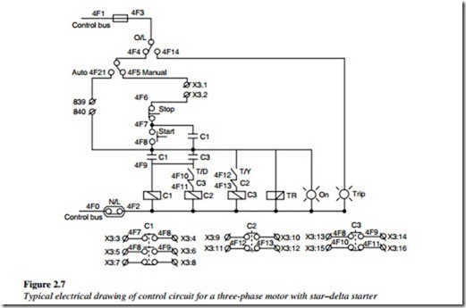
The control circuit as shown in Figure 2.7, for the motor, works on a 110 V AC single- phase supply. The phase of the control supply is connected to a NC contact of the overload relay (O/L). The wire from the O/L relay contact is connected to an auto/manual mode selector switch.
In an auto mode, the motor gets a start/run command through a potential-free contact of a relay, which in turn is energized with a PLC output.
In the manual mode, the motor can be started with the help of a start pushbutton. When the start pushbutton is pressed momentarily, the control circuit is completed and the line contactor is energized. A potential-free NO contact of the line contactor is closed and keeps the control complete when the start pushbutton is released. When the motor is started, the star contactor is closed and the motor is started with a star connection. As the motor runs for a few seconds, the delta timer picks up, which energizes the delta contactor and de-energizes the star contactor. The motor continues to run, connected in the delta configuration, until it is stopped with the stop pushbutton or trips due to an overload or an external interlock.
As can be viewed in Figure 2.7, each contactor used contacts that are given at the end of the drawing. For example, NO contact used is shown with letters 4F7-4F8 and 4F8-4F9 specify their locations in the drawing. Similarly, contact details of contactor C2 and C3 are shown.
Note: The overload relay in this circuit is actually connected in series with the phase winding of the motor in the normal running mode (i.e., delta connection). The motor rated current is normally indicated in terms of the line current which is greater than the phase current by a factor of 3 . Selection and setting of the overload relay must take this into consideration.
Example 2.4
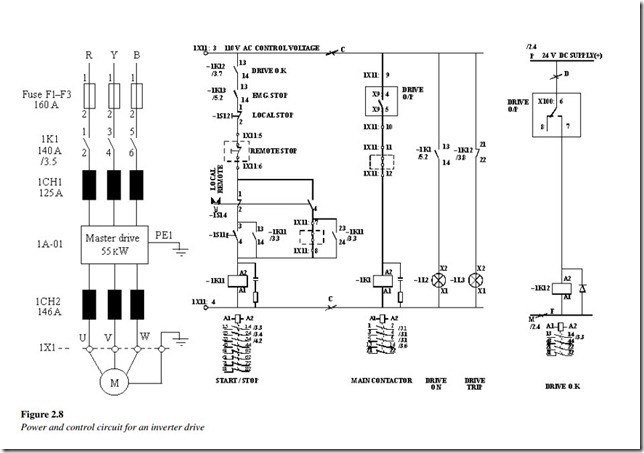
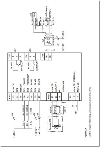
Let us consider electrical drawings of an inverter drive, as shown in Figures 2.8 and 2.9.
Figure 2.8 shows the power circuit wiring for the motor and control circuit wiring for starting and stopping the motor. The three-phase power supply is passed through the fuses and a contactor (1K1) and is connected to an incoming choke (CH1). The output of the choke (CH1) is connected to the input terminals of the inverter drive. The inverter drive gets its main power only when the contactor (1K1) is on. The inverter drive output supply is connected to an output choke (CH2) and the output of the choke (CH2) is connected to the three-phase motor terminals. The inverter drive and the motor are earthed.
The control circuit for the inverter drive works on a 110 V AC single-phase supply. The control circuit for contactor (1K11) consists of the following series of potential-free
contacts:
1. Drive OK (NO contact of 1K12)
2. Emergency stop (NO contact of 1K13)
3. Local stop pushbutton (NC contact)
4. Remote stop pushbutton (NC contact)
5. Local/remote selector switch changeover contacts
6. Start pushbutton (NO contact).
The contactor 1K11 is energized when the control circuit is completed.
The contactor 1K1 is energized, when the drive output contact is closed and additional interlocks connected between the terminals 1X11:11 and 1X11:12 are OK.
A NO contact (13–14) of 1K1 is used to turn on the indication lamp (L2) to indicate that the drive is on. An NC contact of 1K1 is used for indicating a drive trip by turning the lamp (L3) on.
Another contactor (1K12) is energized to indicate drive OK, using a 24 V DC supply through a potential-free contact drive O/P (Terminal X100: 6–7).
Figure 2.9 shows the wiring diagram for the inverter drive control terminals. The inverter drive has the following sets of terminals:
• X100: Contacts for drive OK status
• X101: For start/stop (13–16), reset faults (13–18) commands to the inverter drive
• X102: For remote speed reference (25–27–28) for the inverter drive and analog outputs for speed indication (34–35)
• X9: Main contactor ON (4–5) and power supply (1–2) for external use.
As shown in the figure, terminal grouping is based on different operational functions. For example, digital contacts of drive are grouped with letter X101; whereas analog speed reference input and rpm display output are grouped with letter X102.
Related posts:
Incoming search terms:
- contactor symbol
- how to under stand electric and electronic timersand relays and how to wire it
- Electrical Equipment
- symbol of contactor
- 3 phase isolator symbol
- 3 phase contactor symbol
- no nc contactor wiring diagram
- contactor schematic symbol
- symbol for contactor
- dol with trip pilot lamp
- diagram of dol starter with selector
- selector switch symbol
- 3 phase symbol
- contactor symbol electrical
- 852 Printed Circuit Boards CO LTD Email: @126 com mail
- contactor symbol diagram
- 3 phase symbol of contacter
- m c b electrical drawing symbol
- contactor drawings
- circuit with contactor
- potential free contact circuit diagram
- drawing of low voltage concrete electric pole
- drawings that represent understanding
- symbol of control panel drawing
- drawing symbol for analog switching device
- dc motor notation on drawings
- electrical symbols LT motor power and control drawing
- electrical contactor symbols
- draw the single lin e and wiring diagram of three lambs connectected in series and parallel?
- 1 phase contactor symbol
- among us how to get symbols on electrical
- raditional wiring for circuit breaker symbol
- dol starter with auto manual switch
- how connection of selector switch IN DOL STARTER
- electrical symbol for contactor
- emergency switch symbol
- Breaker and contactor mail
- how to read schneider drawings
- no nc contact symbols
- 25 27 electrical symbol
- contactor electrical symbol
- symbol of Power circuit breaker
- electrical symbol
- three phase circuit breaker symbol
- drawing of a schematic symbol of a star deltar connedtions
- how to read a swucth no nc com
- dol drawing
- electric connections symbols long line
- DG neutral isolation contactor single line drawing
- electrical timer drawing
