Control circuits are very seldom drawn or designed as a complete unit. Rather, they are developed one step at a time to provide for each control function that they will be expected to perform . It is very much like writing a letter when the writer has the general subject that he wishes to convey in mind. He proceeds , sentence by sentence, to put this idea on paper. The same pro cedure should be followed in developing a control circuit. You must have all of the control functions in mind when you start, so as to provide for each function in its proper relationship to all other functions as the circuit is developed.
6 ·1 TYPES OF CONTROL CIRCUITS
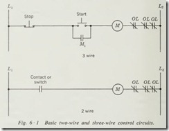
There are two basic types of control circuits: three-wire circuits and two-wire circuits. These designations stem from the fact that for three-wire circuit control only three wires are required from the ordinary across-the-line motor starter to the control components, and in the two-wire circuit only two wires are re quired (Fig. 6 ·1).
The three-wire control circuit requires that the primary pilot control components be of the momentary-contact type, such as momentary-contact push buttons. Maintained-contact devices, such as limit switches and float switches, may be used in various parts of the circuit to supplement the primary start and stop control devices. This type of control is characterized by the use of the auxiliary contact on the starter to maintain the coil circuit during the time that the motor is running.
The two-wire control circuit uses a maintained-contact pri mary pilot-control component, which may be a simple single pole switch, a maintained-contact push-button station, or any type of control component which will close a set of contacts and maintain them in that position for as long as the motor is to be running. The opening of this contact or contacts stops the motor by dropping out the coil of the starter.
All control circuits, regardless of how complex they may be, are merely variations and extensions of these two basic types. It is the purpose of this chapter to show how each of these basic circuits can be developed into the necessary control of a motor or motors by the addition of contacts or push buttons operated by one or more of the various control components to perform the control functions desired. We shall use the sche matic diagram for development of all control circuits because it is the type of diagram which lends itself most readily to the development of control circuits.
The simplest method for the development of a control circuit is to start with the coil and the overloads. Add the primary start and stop control device, which generally, in a three-wire circuit, consists of a STOP and START push button used in con junction with the auxiliary contact of the starter. To this circuit all contacts or push buttons that are to be used to perform the additional control functions are added one at a time until the final circuit has been developed.
Keep in mind, when considering a three-wire control circuit, that all devices intended to perform the function of stop must be normally closed devices and will be located in series with the original STOP button. All devices which are to perform the function of start must be normally open control devices and will be connected in parallel with the original START button.
Sometimes a circuit requires that two or more normally open contacts or push buttons must be closed before the function of start can be performed. These contacts or push buttons would be connected in series, and then the series connection paralleled with the original start components. If it is desired that several contacts or push buttons will have to be opened before the func tion of stop is performed, then these normally closed contacts or push buttons will be wired in parallel and then connected in series with the line to perform the function of stop.
When there is a definite sequence to the action of the various control components, you should add them one at a time to your control circuit in the same order as their operating sequence.
Be sure to check the circuit for proper electrical operation after each contact or push button has been added to be sure that you have not interfered with the proper function of any control component which has already been placed in the circuit.
If you have mastered the preceding part of this book, you should have the necessary knowledge of control functions, con trol components, and circuit diagrams to begin to learn to de velop control circuits. Until you can develop a circuit to perform desired functions, it is doubtful that you will be able to interpret or analyze someone else’s control circuit as to its proper opera tion and the functions which it is designed to perform.
6 ·2 DEVELOPMENT OF CIRCUIT
In order that the step-by-step method of circuit development can be made more clear to you, we shall consider our first circuit as a series of jobs done at different times to improve the opera tion of the original circuit.
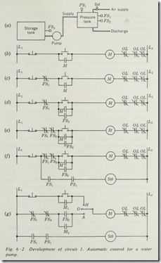
The existing control circuit (Fig. 6 ·2b) is to control a pump which pumps water from a storage tank into a pressure tank. The physical arrangement of the pump and the two tanks, along with the final control components, is illustrated in Fig. 6 ·2a . As the original circuit stands, it is a manual operation requiring that the START button be pushed whenever the water is too low in the pressure tank. The pump is allowed to run until the tank is observed to be full. The operator then pushes the STOP button , securing the pump and stopping the flow of water into the pres sure tank.
The owner now desires that a float switch be installed in the pressure tank near the top so that the operator need only push the START button, thus energizing the pump and starting water to flow into the tank. When the level of the water has reached float switch 1, its contacts will be opened , thus stopping t he pump and the flow of water. The function to be perf ormed by float switch 1 is that of stop. Therefore, it must be a normal ly closed contact and must be connected in series with the origina l STOP buttons, as shown in Fig. 6 ·2c.
After operating with this control for some time, the owner decides that it will be more convenient if the pump is started automatically as well as stopped automatically. He requests that another float switch be installed to maintain the lower level of the tank. This version of the control circuit requires that the pump be started whenever the water reaches a predetermined low level. The control function desired is that of start, so the float switch must have a set of normally open contacts that will be closed whenever the water drops to the lowest desired level. These contacts must be connected in parallel with the original START button so as to perform the function of start for the motor. This connection is shown in Fig. 6 ·2d.
After some time of operating with the new control circuit, it is discovered that occasionally the storage tank drops so low in water level that the pump cannot pick up water. The owner requires a control to prevent the pump from starting whenever the storage tank is low in water. Even though this control does not necessarily stop the pump while it is running, it must prevent its starting whenever the water is low. It must also stop the pump if it is running and the water reaches this low level in the storage tank. Thus, the new control performs the function of stop for the pump.
This function of control can be obtained by the installation of a float switch to sense the extreme low level of water in the storage tank. Float switch 3 was installed and adjusted to open a set of contacts whenever the water in the storage tank reached the desired low level. Because the control function to be per formed is that of stop, float switch 3 must have normally closed contacts which will be opened whenever the water level drops to the set level of the float switch. It is wired in series with the other stop components, as shown in Fig. 6 ·2e.
Later it is decided that the pressure placed on the line by the pressure tank when it is full is insufficient for the needs of the plant. The owner requests the installation of the necessary components and controls to maintain a pressure on the tank by the addition of the proper amount of air to the top of the tank. In order for the proper balance of water level and air pressure to be maintained at all times, air must be let into the tank only when the water level is at its highest position and the pressure is under the desired discharge pressure of the tank.
In order to achieve this, suppose that we install a solenoid valve in the air-supply line which will allow air to flow into the tank only when the coil of the solenoid valve is energized. Now we can install a pressure switch in the top of the tank which will sense the pressure in the tank at all times. This pres sure switch will perform the function of start for the solenoid valve. When the pressure is lower than the set point of the pres sure switch, its contacts must close and complete the circuit through it to the solenoid. If, however, the water is below its top level when the pressure drops, we do not want the solenoid valve to open. Therefore, we require the function of stop in regard to water level, to prevent air being put into the tank when it is not desired.
If float switch FSl is of the double-pole variety, having one normally open and one normally closed set of contacts, we can wire it into the circuit as shown in Fig. 6 ·2/. The circuit for the solenoid valve is a two-wire control circuit requiring that both FS1 and pressure switch PSl be closed in order that air will be placed in the tank by the energizing of the solenoid valve. When the water level reaches its highest point, FSl will be activated. The normally closed contact in the pump circuit will open and the normally open contact in the solenoid circuit will close. If the air pressure is low, the contacts of PS 1 will be closed and air will flow into the tank until either the water level drops and opens FSl or the pressure increases to normal and opens PSI, thus satisfying the requirements of the control circuit as specified by the owner of the plant.
While the circuit of Fig. 6 ·2/ gives a degree of hand operation because the push buttons were left in the circuit, it will be prefer able to have either a definite hand operation or a definite auto
matic operatio n, as desired by the operator. The necessary changes required to give hand, off, and automatic operation to the circuit are shown in Fig. 6 ·2g.
If you had been charged with the responsibility of developing the final circuit of Fig. 6 ·2g, you would have had certain speci fications or requirements as to the proper function or operation of the completed circuit. The first of these probably would have been that it have hand, off, and automatic control selection, the second that the pump be controlled so as to maintain the water level in the pressure tank between a high and low point, third, that the pump be prevented from running whenever the water levels in the storage tank were below a given point, and fourth, that the pressure on the pressure tank be maintained by adding air to the tank whenever necessary. To develop this circuit properly from this set of specifications, the procedure would be the same as that we have followed, assuming that the circuit was built up a little at a time by going back and adding control components to the original manual circuit.
6 ·3 DEVELOPMENT OF CIRCUIT 2
Our second circuit will be for the control of three conveyors so arranged that conveyor 1 dumps material onto conveyor 2, which in turn dumps its material onto conveyor 3, which is used to load trucks or other vehicles at the shipping dock or a warehous e.
The specifications for the operation of the circuit are:
1. One push button is to start all conveyor motors in sequence from 3 to 1 or, in other words, from the last to the first.
2. An overload on any conveyor will stop all conveyors.
3. One STOP button will stop all conveyors in sequence from 1 through 3 or, in other words, from first to last.
An additional requirement is that there be a 2-minute delay between the stopping of each conveyor in the sequence in order that the material on the following conveyor might clear each conveyor before it is stopped.
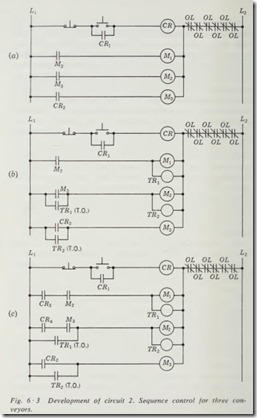
If we are to develop this circuit step by step, then our first step is to meet the requirements of specification 1 that a single push button start all conveyors in sequence starting with con veyor 3. The circuit for this will be found in Fig. 6 ·3a. Here you will find a control relay which is started and stopped by a three-wire push-button control. It is maintained during the run operation by a set of contacts on the control relay, identified on the drawing by the letters CR 1. Since conveyor 3 is required to be the first conveyor to start, the contacts identified on the drawing by CR2, which are closed by the control relay, are connected between the starter coil and the line, giving two-wire control for conveyor 3. This conveyor will start when the control relay is energized and stop when the control relay is deenergized.
In order that conveyor 2 be prevented from starting until conveyor 3 is running, we can use the auxiliary contacts on starter M3 for conveyor 3 to energize the coil of conveyor 2. These contacts are identified as M3 to indicate that they are closed by energizing coil M3. The use of this contact satisfies the condition that conveyor 2 start in sequence, following con veyor 3.
By the same token, if we use the auxiliary contact of the starter for conveyor 2 to energize the starter of conveyor 1, it must follow in sequence behind conveyor 2. The contacts identified on the drawing as M2 are connected in series with the coil M1 for conveyor 1, thus satisfying the condition that conveyor 1 start after conveyor 2 in its proper sequence. We
have now satisfied the conditions of specification 1 and are · concerned with specification 2, which requires that an overload on any one conveyor will stop all conveyors.
The conditions of specification 2 can be obtained by series connection of all overload contacts between the line and each of the starter coils and the coil of the control relay, as indicated in Fig. 6 ·3a. If any one or more of these six overload contacts open, the control circuit to all coils is broken, thus deenergizing the coils and stopping all the conveyor motors at the same time. We have now fulfilled the requirements of specification 2.
While the circuit of Fig. 6 ·3a satisfies the first and second specification, it does not meet the conditions of specification 3 that conveyors stop in the reverse order. The requirement that the conveyors stop in reverse order and that they have a 2-minute time delay between the stopping of each conveyor in sequence indicates the use of timing relays with time opening (TO) contacts. The first inclination is to connect them as indi cated in Fig. 6 ·3b. A careful study of this circuit, however, should reveal to you that when the STOP button is pushed, the control relay will drop out, opening contacts CR1 and CR2, which will only result in the control relay being deenergized, because contact M2 is still closed, maintaining the circuit to coil M 1, contact M3 is still closed, maintaining the circuit to coil M2, and contact TR2 is closed, maintaining the circuit to coil M3. Thus, all conveyor motors continue to run. A modifica tion of this circuit must be made in order that the conveyors may be stopped by the pushing of the STOP button .
In order to satisfy condition 3 of the specifications, the circuit, Fig. 6 ·3b, must be modified as indicated in Fig. 6 ·3c. In this circuit we have added two contacts, normally open, operated by the control relay and identified on the drawing as CR3 and CR4. Now when the STOP button is pushed, the control relay drops out, opening all its contacts and isolating each conveyor motor starter from the line except for the time-delay relay con tacts, which are held closed by time-delay relay 1 and time-delay relay 2. The -opening of contact CR3 breaks the circuit to coil M 1, thus stopping conveyor I. The contact identified as TR1 is· time opening; therefore the circuit to coil M2 is maintained for a period of 2 minutes, which is the setting of time-delay relay 1. At the end of this 2-minute period, the contact TR 1 will open and drop out £oil M2, thus stopping the second conveyor in accordance with the specifications. This starts the timing action of time-delay rel yr 2, and after a period of 2 minutes its.contact (TR2) will open and drop out coil M3, thus stopping conveyor 3.
We have now satisfied all the specifications for this circuit. The conveyors will start in sequence, beginning with 3 and progressing to 1 by the pushing of the single START button. Any overload on any conveyor will drop out all starter coils, thus stopping all conveyors. When the STOP button is pressed, the conveyors will stop in the reverse order to that in which they started, with the delay of 2 minutes between the stopping of each conveyor.
This circuit performs the functions of start, stop, sequence control, overload protection, and time-delay action. The use of the control relay with its three-wire control circuit provides low voltage protection not possible with the two-wire control circuit to each of the conveyor starters.
6 ·4 DEVELOPMENT OF CIRCUIT 3
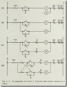
This circuit will be for forward and reverse control of a motor. The specifications state that it must have three-wire control to give low-voltage protection. It must have electrical interlock, and the STOP button must be pushed in order to change direction of rotation of the motor. The first step in the development of this circuit is to provide start and stop in the forward direction. The circuit for this is shown in Fig. 6 ·4a. You will notice that this is the ordinary three-wire push-button control circuit and satisfies the requirement that the motor start and stop in the forward direction with three-wire control.
The second provision of the circuit is that it start and stop in the reverse direction, which is accomplished by the addition of a START button and auxiliary contact as shown in Fig. 6·4b. The START button is wired behind the STOP button so that only one STOP button will be required to stop the motor, regardless of the direction in which it is running.
The requirement that electrical interlock be used is satisfied by the addition of the contacts shown in Fig. 6 ·4c and identified by the letters R2 and F2 , which are auxiliary contacts on the forward and reverse starters. The normally closed contact R2 will be opened whenever coil R is energized, thus preventing coil F from being energized at the same time. Contact F2 will be open whenever coil F is energized, thus preventing the reverse starter from being energized at the same time. This circuit satisties fully the specifications that the motor be able to start and stop in either the forward or reverse direction and that the STOP push button must be pressed in order to change from forward to re verse or from reverse to forward . Electrical interlock has been provided so that both starters cannot be energized at the same time.
Suppose now that plugging reversal is required on this ma chine. The circuit would have to be modified as shown in Fig. 6 ·4d. The START push buttons for forward and reverse would need to be of the double-pole type, having one set of normally open and one set of normally closed contacts. When we push the forward START button, it closes the circuit for the forward starter and at the same time breaks the circuit for the reverse starter. When the reverse START push button is pushed, it not only will complete the circuit to the reverse starter but also will break the circuit to the forward starter, thus giving plugging action.
This circuit performs the control functions of forward-reverse control, start, stop, interlock, overload protection, plugging, and low-voltage protection.


