DEVELOPING A WIRING DIAGRAM
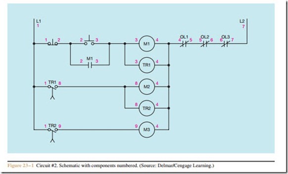
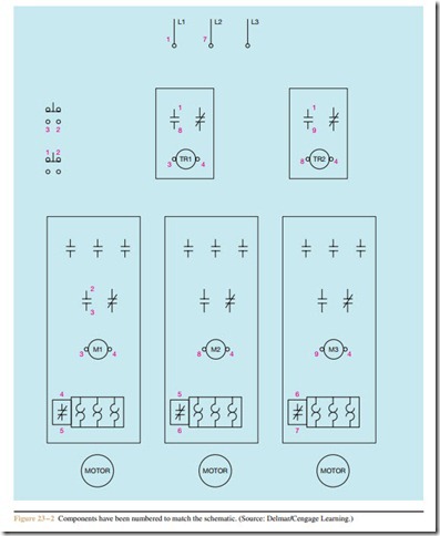
Circuit #2, shown in Figure 23 – 1, is the same as the schematic shown in Figure 20 – 1, except it has been labeled with numbers. Figure 23 – 2 shows the com- ponents of the wiring diagram. The numbers used to label the components in the wiring diagram correspond to the numbers in the schematic. For instance, the schematic shows the numbers 1 and 8 beside normally open contact TR1. The wiring diagram also shows the numbers 1 and 8 beside normally open contact TR1.
The numbers used with each component shown on the schematic have been placed beside the proper component shown in the wiring diagram.
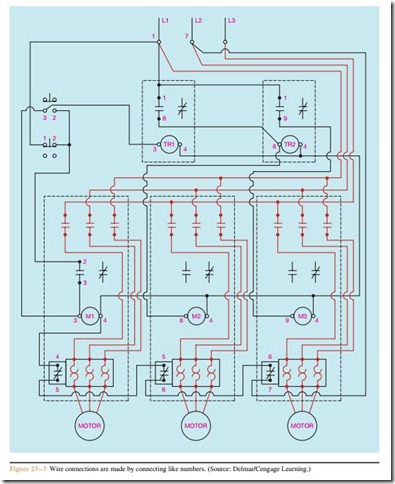
Figure 23 – 3 shows the wiring diagram with connected wires. Notice that the wiring diagram shows motor connections while the schematic does not. Al- though it is a common practice to omit motor connections in control schematics, wiring diagrams do show the motor connections.
Review Question
1. Referring to the circuit shown in Figure 23 – 1, would it be possible to change the components that have been numbered with an 8 to a number 9,
and the components that have been numbered with a 9 to a number 8, without affecting the operation of the circuit?


