Magnetic Controllers
Magnetic controllers or starters are classified according to their control features, as:
1. Semiautomatic,
2. Automatic.
Semiautomatic control requires manual actuation, such as an operator pushing a button for START, STOP, INCH, FORWARD, or RE VERSE. An automatic starter, on the other hand, functions without human actuation and exists wholly due to special conditions and design features. An example is a motor-operated float switch, a pressure operated switch, a time-limit switch, etc.
Magnetic controllers are again classified according to the accelerating features, as:
I. Definite time Iimit,
2. Current limit,
3. Counter-emf.
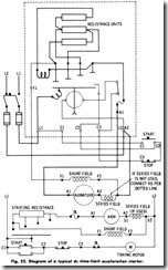
Definite Time-Limit Starters-Time-limit starters (Fig. 22) are sim ple in construction, accelerate the motor with low current peaks, use less power during acceleration, and always accelerate the motor in the same time regardless of variations in load. Definite time delay may be obtained in one of several ways. A pawl-and-ratchet mechanism at tached to the gears of a timing device permits the solenoid to operate at a predetermined moment. An escapement mechanism is another way of obtaining time delay.
Inductive time-limit acceleration makes use of the inductive time-lag effect of the decay of current a heavily inductive circuit. Sometimes called magnetic timing, the inductive time-limit contactors may be of the normally open hold-out type, or of the normally closed type. In a similar manner, capacitor time-limit acceleration makes use of the constant discharge time of a capacitor in the sequence operation of accelerating contactors.
Standard magnetic accelerating equipment is available in ratings up to 150 hp (111.9 kW) for reversing or nonreversing service, and with or without dynamic braking, Braking can be obtained by several methods. Dynamic braking makes use of a discharge resistor placed across the motor terminals after the main contactor has disconnected the motor from the line. Plugging is obtained by reversing the armature connec tions while running, and accomplishes a very rapid reversal of the armature. Magnetic brakes are used to obtain quick, accurate stopping and to hold the load after stopping. Most brakes are electrically released and spring-set, so that braking will be obtained even though an electrical failure should occur.
In addition to overload and low-voltage protection, other types of protection are often required. Over speed or underspeed protection can be obtained by means of centrifugal governors or tachometers. Control functions may thus be initiated at any predetermined speed value to accomplish any desired reaction.
Field-failure protection is usually provided to disconnect the motor from the line in the event of an open shunt field in either shunt or compound motors. A relay coil is connected in series with the shunt field to give the signal on an open-field condition.
Field-protective relays are often used to insert resistance in series with the shunt field when the motor is not in operation, thus preventing overheating of the shunt field while the motor is at a standstill. When shunt-field circuits must be opened, field-discharge resistances should be provided to limit induced voltage to a value that will not damage the field-winding insulation when the field circuit is open.
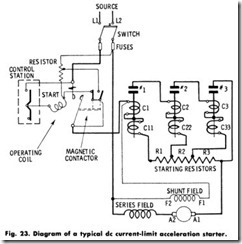
Current-Limit Starters-Acceleration by current limit depends wholly on values of the armature current, and contactor operation may be regulated to any predetermin d value. For example, when the START button is pressed and the main-line contactor closes with all the starting resistance in the circuit, a certain value of inrush current (say 150%) is encountered, which finally decreases to some other value (say 115%). At 115%, the first accelerating contactor closes, shorting out part of the resistance, and the inrush current immediately increases, only to decrease again as the motor speed picks up. This increases the counter emf, and the second accelerating contactor closes when the current decreases to the preset value, etc.
Current-limit acceleration is entirely dependent on load. Light loads will accelerate rapidly, while heavier loads will require a longer time. For this reason, current-limit starting is not so satisfactory for varying loads. It is entirely possible that, under heavy-load starting, the speed will not pick up to the point where the current will be reduced enough to actuate the succeeding accelerating contactor. Thus, the motor will operate at the point with starting resistance still in the armature circuit. Current-limit starting is most desirable for motors driving high inertia loads. Fig. 23 shows the diagram of a typical current-limit acceleration starter.
Counter-emf Starters–Counter-emf acceleration uses a form of current-limit acceleration. The acceleration contactors close in suc cession as the voltage across the armature increases, until the motor is
finally brought up to full speed with the closing of the last accelerating contactor. This type of control (Fig. 24) is usually limited to motors rated up to 5 hp.
Advantages of Magnetic Controllers-Magnetic controllers are gen erally used because of their advantage over other forms in that the acceleration (time element) required for the motor starting is removed from the physical effort of the operator. With the faceplate type of controller, for example, the operator may accelerate the motor too rapidly, resulting in the motor taking excessive current. This usually results in burned-out fuses or resistances, or the opening of circuit breakers.
With magnetic controllers, the starting resistance may be cut out at the maximum safe rate by means of magnetically operated switches. The operator’s duty is to push a button; the magnetic switch starts the motor and accelerates it by cutting out the starting resistance. In stopping or reversing the motor, pressing the button marked STOP or REVERSE opens or closes the correct contactor or contactors to perform the desired operation.
Magnetic starting is especially adapted to frequent starting opera tions-when the motor is located at some distance from the operator, when space does not permit mounting a manual controller near the operator, or when large motors require commutation of heavy circuits.
DC-MOTOR TROUBLE CHART
SUMMARY
Direct-current motors are classified as: (1) series-wound; (2) shunt wound; and (3) compound-wound. In series-wound motors, the field coils and armature are connected in series, and the entire current flows through the field coils. In the shunt-wound motor, the field coils and the armature are connected in shunt (parallel); therefore, the field current is only a small portion of the total or line current. The compound-wound motor incorporates both the series-wound and the shunt-wound windings.
In construction, all de motors have a stationary field member (frame or yoke) and a rotating armature member. The frame, which is made of cast or fabricated steel, serves as a support for the motor and is a part of the magnetic circuit connecting the field poles and the commutating poles. The armature is made of wire-wound coils embedded in parallel slots on the surface of the armature core.
The series motor is suitable for applications where it is necessary to supply a large torque with a moderate increase in current, such as in traction work, crane operation, etc. The speed varies greatly with a change in load. Since there is a possibility of dangerously high speed at light loads, the series motor is not suitable for belt drive or where the torque may drop below 15 percent of full-load torque.
The shunt motor operates at nearly the same speed at any load within its capacity, and slows only slightly when greatly overloaded. There is only a slight drop in speed from no load to full load. Shunt motors without speed control are used to drive machinery that is designed to run continuously at a constant speed.
A compound motor is produced by adding a cumulative series field winding to the shunt field. The speed changes with the load, but the change is less than in the series motor and much more than in a shunt motor. Thus, heavy loads can be started, as with the series motor yet, like the shunt motor, the compound motor will not “run away” with light loads.
Compound motors are commonly used for elevators, air compressors, ice machines, certain types of hoisting and conveying machinery, printing presses, paper cutters, pumps, and other machinery where the load fluctuates suddenly or periodically and where constant speed is not essential.
De motor controllers are divided into two types: ( 1) manual; and (2)magnetic. Three types of manual controllers are faceplate, multiswitch, and drum controllers. The magnetic controllers are semi-automatic and automatic.
REVIEW QUESTIONS
1. . What are the three types of de motors?
2. Describe the types of windings found in the various de motors.
3. Describe the operating characteristics of the various de motors.
4. What factors determine the speed of a de motor?
5. List the uses for the compound motor.


![DC-MOTOR TROUBLE CHART_thumb[2] DC-MOTOR TROUBLE CHART_thumb[2]](http://machineryequipmentonline.com/electric-equipment/wp-content/uploads/2020/06/DC-MOTOR-TROUBLE-CHART_thumb2_thumb.jpg)
![DC-MOTOR TROUBLE CHART1_thumb[1] DC-MOTOR TROUBLE CHART1_thumb[1]](http://machineryequipmentonline.com/electric-equipment/wp-content/uploads/2020/06/DC-MOTOR-TROUBLE-CHART1_thumb1_thumb.jpg)
![DC-MOTOR TROUBLE CHART2_thumb[1] DC-MOTOR TROUBLE CHART2_thumb[1]](http://machineryequipmentonline.com/electric-equipment/wp-content/uploads/2020/06/DC-MOTOR-TROUBLE-CHART2_thumb1_thumb.jpg)
![DC-MOTOR TROUBLE CHART3_thumb[3] DC-MOTOR TROUBLE CHART3_thumb[3]](http://machineryequipmentonline.com/electric-equipment/wp-content/uploads/2020/06/DC-MOTOR-TROUBLE-CHART3_thumb3_thumb.jpg)
![DC-MOTOR TROUBLE CHART4_thumb[1] DC-MOTOR TROUBLE CHART4_thumb[1]](http://machineryequipmentonline.com/electric-equipment/wp-content/uploads/2020/06/DC-MOTOR-TROUBLE-CHART4_thumb1_thumb.jpg)