Checking Clearance by Micrometer Method
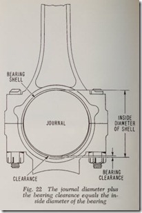
Before explaining the microm eter method of deciding what size bearing to us e, it is necessary to discuss bearing diameters, jou rnal diameters and specified bearing clearances, Fig. 22.
Standard size bearing shells are m ade so that their inside diameter equals the maximum journal diameter plus the minimum specified bearing clearance. For example, if the maximum journa l diameter is 2.1250” and the minimum specified bearing clearance is .0005″, then the inside di ameter of the bearing is 2.1255″.
If a standard size bearing shell has an inside diameter of 2.1255″ as mentioned above, the un dersize bearings are so many th ousandths less than this figure. Therefore the .002″ undersize would be 2.1235″ and the .010″ undersize would be 2.1155″, and so on.
Likewise if the minimum specified bea ring clear ance is .001″ and the maximum diameter of a new journal is 2.125″, the inside diamet er of the bear ing is the sum of the two figures or 2.126″. The
.002″ undersize would be 2.124″ and so on.
It is impossible to make any pa rt of any machine-a bearing journal for example-to perfect accuracy such as 2.125″-no more and no less. Therefore most car makers usually allow a toler ance of .001″ although a few use a tolerance of .0005″. Thus the journal diameter might vary from 2.125″ to 2.124″.
The dimensions just given for a 2W’ rod jour nal, namely 2.125″ to 2.124″ mean that in a new engine of this particular make the journals may have a diameter of 2.125″ or 2.124″ or anywhere in between these limits. In other words the journal tolerance is said to be .001″. –
Likewise bearing clearance has a tolerance range, for example, .0005″ to .0015″. This means that a clearance of less than .0005″ is considered too little and a clearance of more than .002″ is too much.
·whether to install a standard size rod bearing or a .001″ to .002″ undersized bearing can be readily determined by a micrometer-without the use of shim stock or Plastigage except perhaps as a final check when the new bearings are installed. The check is insurance against a bearing whose size is not what it is supposed to be. The check also shows up any errors in reading the microme ter. This method has the advantage that the cor rect bearing size can be selected with the certainty that it will fit. No time is wasted trying first one bearing size and then another.
The first step is to measure the rod journal for out-of-round and taper, as already described, to decide whether or not the journal should be re ground.
If journals do not need regrinding, the next step is to decide whether standard size bearings or .001″ or .002″ undersize will provide the best fit.
Which of the three sizes of bearings to install depends on the maximum diameter of the worn rod journal. If the rod journal when new had a nominal diameter of 2.125″, use a standard size bearing if the journal diameter measures between 2.125″ and 2.124″.
If the rod journal diameter is between 2.124″ and 2.123″, use a .001″ undersize bearing, if avail able.
If the diameter is between 2.123″ and 2.122″, use a .002″ undersize bearing.
Fit a standard size bearing if the diameter of the worn journal is not more than .001″ under par.
Checking Clearance by Plastigage Method
Plastigage is placed on the lower half of the bearing, Fig. 23, and the cap is installed and tightened to the specified torque. This flattens the Plastigage to whatever the bearing clearance is. The cap and bearing are removed.
The greater the width of the strip the less the bearing clearance and vice versa. The paper scale measures the clearance in thousandths of an inch. Actually the scale can be read to 3 thousandth or less.
Plastigage is intended to be used for checking worn bearings and also for checking newly in stalled bearings to make sure that the clearance is within the required limits.
The Plastigage comes in a sealed envelope. It is made for three ranges of bearing clearances each with a different color of wax, as follows: Green,
.001″ to .003″; red, .002″ to .006″; blue, .004″ to .009″. The blue is intended for very large crank shafts. For automobiles, the red range is usually used for checking worn bearings. But if new undersize bearings are installed, it may be neces sary to use the green range to determine whether or not the new bearing is too tight. Bear in mind that the green range measures as little as .001″ clearance while the minimum for the red range is .002″.
Before using Plastigage, clean the journals and the bearings so that all oil is removed. The Plasti gage is soluble in oil and therefore oil will affect the accuracy of the reading.
Do not rotate the crankshaft when using Plasti gage.
As explained previously, a rod journal wears more vertically than horizontally. Consequently if Plastigagc is placed at the center of the bearing with the rod at lower dead center, maximum clearance will be registered. Likewise, clearance is a minimum at 90 degrees from this point. Best results are obtained if bearing clearance is mea sured at the halfway point. The rod journal is placed 30 degrees from lower dead center and.the Plastigage is placed W’ away from the vertical axis.
To decide whether to instal! a standard size bearing or .001″ or .002″ undersize compare the clearance indicated by the flattened Plastigage with the specified clearance. For example, let us assume that this clearance is .0005″ to .0025″.
If the Plastigage reading is about .003″ or less,try a standard size bearing. Install the bearing and check with Plastigage. If the clearance is less than the specified .0025″, the clearance fit is okay.
If the Plastigage reading is .0035″ more or less,try a .002″ undersize bearing which reduces the clearance to .0015″.
If the clearance is .0025″ to .0030″, try a .001″undersize bearing if available.
If an undersize bearing is installed be sure that it is a free fit on its journal. If not, the bearing is too small.
For main bearings, the procedure is the same as for rod bearings except the crankshaft can be checked in any position.
When checking main bearings with Plastigage,all caps should be tight.
If the bearings are badly worn, a paper shim should be installed in each main bearing except the one being checked. Otherwise the weight of the crankshaft will press down on the Plastigage and therefore the Plastigage reading will be too small.
TAPER SHIMS FOR WORN BEARINGS
Shimming Worn Bearings
Efforts have been made to economize by re using worn bearings with thin shims between the bearing back and the housing to compensate for wear. Very often this method is not successful, and it is not recommended.
One of the problems in attempting to make this kind of adjustment is that bearings do not wear round. The heaviest loads occur near the area of the crown of each bearing half (at right angles to the parting plane of the bearing). Therefore wear is greatest in this area. As a result, adjustment with shims of uniform thickness reduces the bear ing inside diameter all the way around. In some sections the diameter is reduced too much, caus ing insufficient oil clearance and consequent oil starvation.
Tapered shims, that are thickest at the crown area and thinner close to the bearing parting faces, have also been used. But because bearings do not wear exactly oval either, th e use of these
shims often results in non-uniform oil clearance.
Any shim between the bearing ba ck and hous ing has another effect. That is, they increase the bearing crush drastically, often resulting in per manent distortion of the bearing shell.
CLEAN ENGINE OIL PASSAGES
Before installing new bearings it is desirable to clean out the engine oil passages in both cylinder block and crankshaft. · Also clean the inside of the crankcase and the oil pan.
If the engine is in the car, use kerosene or a special solvent in conjunction with compressed air to blow out the passages. Automo tive jobbers can supply you with a suitable nozzle-a nd a special solvent.
If the engine is out of the car, the cylinder block and crankshaft should be soaked in a special cleaning tank before any work is done on either the block, the crankshaft or any other engine parts. When dirt has been loosened up, blow out all oil passages in the block and crankcase with compressed air. If this cleaning equipment is not available, use the method described in the preced ing paragraph.
Whenever there are oil passages to be cleaned, a rifle brush, Fig. 24, can be used in conjunction with any of the methods described above. Or, if necessary, the rifle brush can be used alone. Wet the brush with a suitable solvent or, if possible, submerge the shaft in solvent and allow it to soak for a few minutes. Then use the rifle brush.
ROD BEARINGS, INSTALL
Upper and lower bearings may be identical or the upper and lower bearings may have different oil grooving. If the rod has an oil spurt hole and a drilled passage to lubricate the piston pin there will be holes in the upper bearing half to allow the delivery of oil to the spurt hole and the drilled passage. Therefore, when assembling the upper half of the bearing to the rod be sure that the holes arc properly aligned.
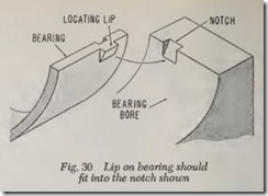
When installing each bearing half, be sure that the lip on one edge of the bearing is accurately seated in its notch in the rod or cap.
BEARING SPREAD
Both main and rod bearings are made with a slight spread so that they will stay in place in the bearing bore or bearing cap when inserted. This makes for ease of installation. If a thin shell bearing does not have enough spread to stay in place, expand it by pulling slightly on the ends with the fingers.
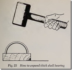
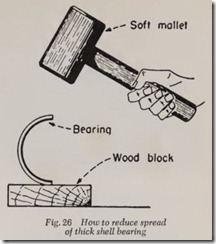
If the bearing is a thick-sh ell type it can be expanded by placing on a Hat surface, Fig. 25, and tapping it with a soft mallet. If thick shell bearing has too much spread, reduce spread by tapping it as shown in Fig. 26.
BEARING CRUSH FIT
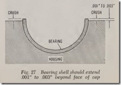
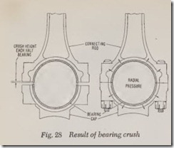
The lower halves of thin shell rod or main bear ings should project slightly ( .001″ to .003″) above the Hat face of the cap, Fig. 27. The purpose of the projection is to compress the bearing into the bore to seat the outside of the shell tightly against the cap. Intimate contact is necessary not only to conduct heat away from th e bearing but also to provide a firm support for the heavy loads im posed on the bearing, Fig. 28.
ROD SIDE CLEARANCE
Be sure that the rod does not bind endwise on the crankshaft. For safety there should be a few thousandths clearance, say .004″.
MAIN BEARINGS, REPLACE
To install main bearing shells, remove and replace the bearing caps one at a time. It may facilitate the removal and replacement of the up per shells if all main bearing cap nuts are first loosened f tum.
The upper shell is pushed out of its seat bore by rotating the crankshaft after inserting a flat headed tool (providing bearing shells are not doweled), Fig. 29, in the oil hole in the crank shaft. The thickness of the head must be less than the thickness of the bearing shell. Lacking this tool, the head of a common nail may be used in stead. The oil hole is at an angle and the end of the nail head or tool should be parallel to the journal. One end of the shell has a lip on it which fits into a notch in the bearing bore, Fig. 30. It should be obvious that th e shell should be re moved by pushing on the opposite end. But when installing a new shell, push on the end which has the lip. When the bearing is in place be sure that the lip is accurately seated in the notch. To install the shell, first dip it in engine oil. Then insert the unnotched end in th e notched side of the bearing bore. Push it in as far as it will go by hand and then finish the job by rotating the crankshaft. If a heavy push is required, find out why. Probably the shell was not started squarely.
CHECK BEARING INSTALLATION
When installing new bearings, as described above, check each rod and main bearing after it is installed to be sure it is not too tight. If a bearing binds, it is often due to sharp edges on the sides of the bearing shell in which case, dull the edges very slightly with a scraping tool. There is, of course, also the possibility that the bearings are the wrong size.
If the crankshaft ‘is reground and undersize bearings are installed, it is to be expected that bearings and journals will fit together perfectly and usually they do. But be sure that the crank shaft can be rotated freely when all main bearings have been installed and the caps drawn up to the correct torque wrench readings. Likewise when each rod is installed, see that it can be moved by hand lengthwise on the journal.
If any bearing binds, remove it to determine cause. Always tighten bearing cap nuts to torque wrench specifications. Then check bearings with shim or Plastigage to be sure that the clearance is not too much or too little.
DOWELED MAIN BEARINGS
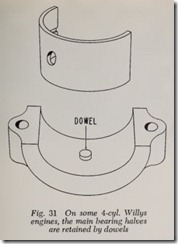
On some 4-cyl. Willys engines, the main bear ing halves are held in place by dowels, Fig. 31. Consequently the upper halves of the main bear ings cannot be removed without removing the crankshaft. Once the crankshaft is out of the way the bearing halves can readily be lifted out.
CRANKSHAFT END PLAY
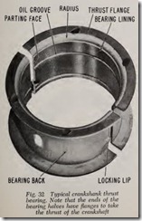
There is a certain amount of endwise thrust on the crankshaft and this thrust is controlled to a speci£ed limit by various means, usually by flanges on one of the main bearings. On cars with manual shift transmission, when the clutch pedal is depressed the crankshaft and flywheel assembly is pushed forward. On automatic transmissions with a torque converter, the thrust is exerted rearward.
However, even if there never was any thrust on a crankshaft a thrust bearing would be desirable in order to confine the movement of the crank shaft lengthwise. Any main bearing may be se lected to function as a thrust bearing by the engine designer.
The endwise motion or clearance at the thrust bearing must be less than the endwise clearance at the other main bearings (and at the rod bearings) because the crankshaft must be allowed to rub against the edges of these bearings or bearing trouble will ensue.
Fig. 32 illustrates a typical thrust bearing. The ends of the bearing inserts are flanged and coated with bearing metal. The adjacent crankshaft faces, of course, are ground smooth the same as is the journal itself.
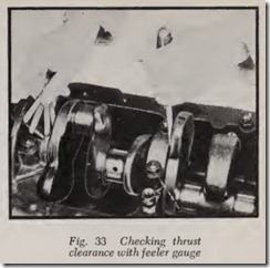
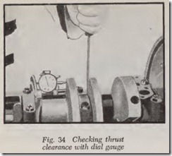
To determine the clearance at the thrust bear ing, pry the crankshaft forward at an adjacent main bearing by means of a screw driver and then check the clearance with a feeler gauge, Fig. 33, or with a dial gauge, Fig. 34.
If new thrust bearing shells are installed, check the clearance. If less than the specified minimum, the bearing flanges may be dressed down to get the desired clearance or a new bearing should be tried. Measure the distance between the thrust faces on the crankshaft with a micrometer. Then subtract the minimum thrust clearance from this length. The difference is the length that the bear ing should be reduced. If the clearance is too great, a new thrust bearing should be installed and clearance checked.
When a crankshaft is reground, it is often nec essary to remove a little metal from the thrust faces on the crankshaft. This may require the installation of a thrust bearing with flanges thicker than standard. The automotive machine shop which grinds the crankshaft should supply a thrust bearing to give the correct clearance.
