All components used in motor-control circuits may be classed as either primary control devices or pilot control devices. A primary control device is one which connects the load to the line, such as a motor starter, whether it is manual or automatic. Pilot control devices are those which control or modulate the primary control devices. Pilot devices are such things as push buttons, float switches, pressure switches, and thermostats.
4·1 DESCRIPTION OF PILOT DEVICES
An example of primary pilot control would be a magnetic across-the-line starter controlled by a simple toggle switch used to energize and deenergize the coil of the starter. When the switch is closed, the starter will be energized and will start the motor. When the switch is open, then the starter will be deener gized and will stop the motor. The starter, in that it connects the motor or load to the line, would be classed as a primary control device. The switch does not connect the load to the line but is used to energize and deenergize the coil of the starter. Therefore, it would be classed as a pilot control device.
For any given motor, generally there are two primary control devices used. These are the disconnecting means or switch and the motor starter. There may be many pilot devices used in parallel and series combinations to control the function of start and stop performed by the primary control device. The overload relays, for instance, which are included in the motor starter, are actually pilot devices used to control the primary device whenever the motor is overloaded.
The requirements of pilot devices vary greatly with their func tion and their proposed use. For instance, a float switch must open and close its contacts on the rise and fall of a liquid in some form of container. A pressure switch must open and close its contacts when the pressure in some vessel, pipe, or other container varies through the limits built into the pressure switch. Perhaps the best picture that can be drawn to show the difference between primary devices and pilot devices would be the compari son of a contactor and a voltage relay. The contactor is built to carry relatively large currents; therefore, it has heavy contacts capable of interrupting these currents. The relay, designed for pilot duty, has relatively small contacts because the current it is expected to interrupt is very small. In general, pilot devices might better be termed sensing devices because they are gen erally used to sense such things as pressure, temperature, liquid level, or the pressure applied to a push button. The function of these pilot devices is to convert the information that they sense into control of the primary control device with which they are connected.
4·2 FLOAT SWITCHES
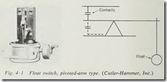
Float switches take many forms in their physical or mechanical construction. Basically, however, they consist of one or more sets of contacts either normally open or normally closed, oper ated by a mechanical linkage. Many float-switch units, as well as other pilot devices, employ a mercury switch in place of metallic contacts. The simplest mechanical arrangement for a float switch (Fig. 4 ·1) would be a pivoted arm having the con tacts fastened to one end and a float suspended from the other end. As the water level rises, it would lift the float, thus, moving the contact end of the lever downward and either making or breaking the contact, depending on whether the stationary con tact were mounted above or below the arm. If a single-pole double-throw action of the contacts were desirable, then one stationary contact could be mounted above, and one below, the center of the arm. If the float were all the way up, it would make the lower set of contacts, and if the float were all the way down, it would make the upper set of contacts.
Float switches require some means of adjusting the range of operation, that is, the amount of float travel between make and break of the contacts. In the simple float switch, this is usually accomplished by suspending the float on a rod which passes through a hole in the arm of the switch itself. Then if stops are placed above and below the arms on the float rod, the amount that the float travels before it operates the switch may be adjusted by moving the stops further apart or closer together.
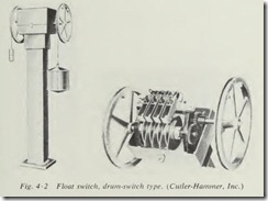
Another system used in float-switch construction to give an even greater range of adjustment is to have the float suspended on a chain or cable which winds up on a reel. The action of the float is then transformed into a rotary motion which actuates a drum-type switch (Fig. 4·2). As may be noted from the ac companying photographs, these are only two of the many possi ble ways that a float may be made to actuate a set or sets of contacts. Any arrangement that will accomplish this may be properly classed as a float switch and used for pilot duty.
It should be noted here, however, that float switches are also made with heavy contacts and are suitable for primary control of small fractional-horsepower motors. When used for primary control, they are inserted in the line leads ahead of the motor and merely make and break the motor circuit in response to the action of the float.
It is highly desirable when studying pilot devices, if it is at all possible, to obtain several units made by different manufac turers and study the mechanical devices employed in their opera tion. The student will find that they vary greatly in actual me chanical design but fall into the same basic type of operation as described herein.
4 ·3 PRESSURE SWITCHES
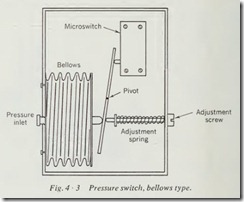
Pressure switches, like float switches, are generally considered to be pilot devices. In the heavy-duty models, however, they are sometimes built for primary control of fractional -horsepower motors. Again, as with all pilot devices, they vary considerably in their mechanical design. Basically, they fall into three general classes according to the means of operation. The first of these is a bellows which is expanded and contracted in response to increase and decrease in pressur e. The contacts are mounted on the end of a lever, which is acted upon by the bellows (Fig. 4 ·3) . The bellows expands, moving the lever, and either makes or breaks the contacts, depending on whether they are normally open or normally closed.
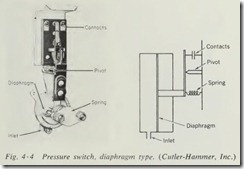
The second general type uses a diaphragm in place of the bellows (Fig. 4 ·4). Otherwise, the action of the switch is identi cal whether it contains a bellows or a diaphragm . The advantage of one type over the other depends greatly upon the installation and the pressures involved and would have to be decided in each installation.
It should be noted that pressure switches have a definite range of pressure where they are designed to operate. For instance, a pressure switch made to operate from a vacuum up to possibly several pounds of pressure would not be suitable for use on a line which normally would carry from 100 to 200 lb of pressure.
A third general type of pressure switch, the bourdon tube, employs a hollow tube in a semicircular shape so designed that an increase in pressure tends to straighten the tube. This action is transformed into a rotary motion by a linkage which trips a mercury switch mounted within the enclosure.
4 ·4 LIMIT SWITCHES
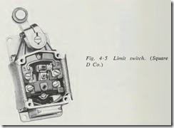
Limit switches are designed so that an arm, lever, or roller pro truding from the switch is bumped or pushed by some piece of moving equipment. The movement of this arm is transformed through a linkage to a set of contacts. Movement of the arm causes the contacts to open or close, depending upon whether they are normally open or normally closed (Fig. 4 ·5).
There is a great variation in the internal design and action of these units, but, again, they fall into two general classifications as to mechanical design. The units intended for rugged use but not for precision control generally have metallic contacts oper ated directly from the lever action of the switch. Most manufac turers build a more accurate, or precision, unit which employs a microswitch to allow operation on very minute movements of the external lever of the switch. As with float switches, there are limit switches which are built so that a cable or chain is wound up on a reel which forms part of the limit switch. This movement of the chain or cable is transformed to a rotary mo tion which actuates a drum-type switch. This type of limit switch is used where a great deal of travel must be allowed between actions of the switch.
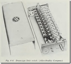
Another type of limit switch (Fig. 4 ·6) which em ploys a drum-type switch is designed for direct shaft mounting where the rotation of the machine directly causes a rotation of the switch. The contacts in this type of limit switch must be designed to resemble a cam so that they can close and open with a con tinuous rotation in the same direction. Many limit switches of this type are coupled through a reduction gear so that many revolutions of the machine are required to produce one revolu tion of the limit switch, thus extending the range of control offered by the limit switch.
4·5 FLOW SWITCHES
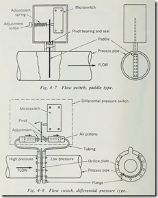
The purpose of a flow switch is to sense the flow of liquid, air, or gas through a pipe or duct and to transform this flow into the opening or closing of a set of contacts. One type of flow switch (Fig. 4 ·7) utilizes a pivoted arm having contacts on one end and a paddle or flag on the other end. The end with the paddle or flag is inserted into the pipe so that the flow of liquid or gas over th is valve causes a lever to move and open or close the contacts .
Another type of flow switch uses a difference in pressure across an orifice flang which is installed in the pipe. A pipe is run from each side of the orifice to a pressure switch. The corresponding difference in pressure actuates the pressure switch in one direction or the other, opening or closing its contacts, depending upon their arrangement. Such a flow switch is illus trated in Fig. 4 ·8.
As with other types of pilot control, there are many other possible mechanical arrangements for flow switches. The student should consult manu facturers’ catalogs and study the diagrams and illustrations in them to acquire a broader knowledge of the design and application of flow switches.
4·6 THERMOSTATS
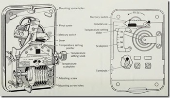
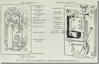
Probably the thermost at is the pilot device which is built in the greatest variety of mechanical arrangements. Some are made to employ the action of the bellows to move the contacts. Some employ bimetallic strips to sense temperature and actuate the contacts. Many other arrangements are possible with this type of unit. A study of Fig. 4 ·9 will help the student to visualize a few of the arrangement s found in everyday use on thermostats. Thermostats for use in motor-control circuits merely open or close a set of contacts in response to temperature changes, re gardless of their mechanica l construction and action.
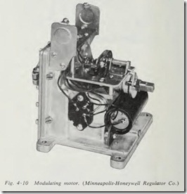
The modulating thermostat moves a contact across a resistance in proportion to the change in temperature, thus varying the relative resistance of the circuit. When properly connected to a modulating motor (Fig. 4 ·10), it can control the position of the motor in direct response to the changes in temperature. The movement of an arm on the motor shaft is directly propor tional to the amount of change in temperature. When connected to a damper, the modulating motor can control the amount of air flowing through a duct. When connected to a valve, the motor can control the flow of water or other liquids or gases through a pipe. While this type of thermostat is seldom, if ever, used for the direct control of a motor, it can initiate control through contacts mounted on the shaft of the modulating motor.
4·7 PUSH-BUTTON STATIONS
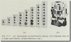
The push-button station (Fig. 4 ·11), while probably the sim plest of all pilot devices , is the most commonly used in motor control circuits. Push-butt on stations are of two general types: the maintained-contact type and the momentary -contact type. When the START button is pushed on the maintained-contact type, the contacts close and remain closed until the STOP button is pushed. This action is accomplished through a mechanical linkage from the button to the set of contacts, which are so ar ranged that they will remain in either position until moved to the opposite position.
The momentary-contact normally open push button, such as used for START buttons, merely closes its contacts for whatever period of time the button is held down. The normally closed momentary-contact push button opens its contacts for whatever period of time the button is held down. Push buttons also are available in the double-pole style. This push button has one set of contacts that are normally closed and one set that are normally open.
Push-button stations are made up of individual push buttons which may be normally open, normally closed, or double-pole units to give whatever combination of contacts that are needed. The most common push-button station is the start-stop station. Push-button stations are available, however, in most standard labelings to cover the norm al control operations and are avail able with special labels to fit special needs. Also found on push button stations are pilot lights to indicate when the motor is run ning, or possibly when it is not running, and selector switches.
A selector switch may be used for hand-off-automatic control, or it may be simply an on-off switch .
4 ·8 PLUGGING SWITCHES
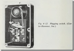
The plugging switch, sometimes referred to as a zero-speed switch (Fig. 4 ·12), is a special control device which is operated by the shaft of the motor or a shaft or pulley turned by some part of the machine. The rotation of the shaft causes a set of contacts to close, and when the power is removed these contacts cause a momentary reversal of the motor. When the motor is running in reverse, the forward set of contacts is closed. When the power is removed, this set of contacts momentarily energizes the motor in the forward direction . This sudden momentary reversal of direction of rotation of a motor is known as a plugging stop. Plugging is used on m any precision machines such as presses, grinders, and other m achine-tool operation. The purpose of plugging a motor is to bring it to an abrupt stop, so the plugging switch must not hold the starter closed for any ap preciable length of time. Before a plugging switch is installed on a motor, it should be determined that the machine and motor are built for this rugged operation and that plugging will not endanger the operator.
4 ·9 TIME CLOCKS
The time clock as used for motor-control circuits consists of an electric clock to drive adju stable cams which open and close contacts at any present time. There are many versions of the time clock in general use. The simplest clock has a set or sets of contacts which can be adjusted to turn the external circuit on once and off once each day. There are severa l more elaborat e versions between the simple time switch and the elaborate pro gram clock. A program clock m ay be used to open and close several circuits independently at any desired time. This clock may also be set to skip undesired days so that a program for a period of time, generally consisting of a week , may be set up on the tape, and the clock will make and break the circuit by opening and closing its contacts at each predetermined time.
Summary
The discussion in this chapter is not by any means a complete list of all pilot devices that are manufactured. We have covered the most common and frequently encountered types. Most
special pilot devices, such as aquastats, stack switches, relative humidity controllers, airstats, high-pressure cutouts, and suction pressure controls are merely adaptations of the basic types that we have discussed. The control man must above all else be able to look at a strange control device and analyze its function both mechanically and electrically so that he will understand its oper ation in a control circuit. A thorough understanding of the basic types of control components will enable you to handle most , if not all, new components that you will find on the job.
The best method of becoming familiar with all types of control components is to make a study of the literature which manufac turers are happy to supply free of charge. This literature gen erally contains photographic illustrations showing the mechani cal and electrical operation of the various devices and is usually accompanied by written description of the operation, ranges, and possible uses of these devices.
Quality should never be sacrificed in control components, par ticularly pilot devices , where the temptation to use cheap com petitive units is the greatest. While a thermostat , float switch, or limit switch seems to be an insignificant part of an overall control system, the failure of one of these pilot devices can shut down the operation of a whole industrial plant. This is especially so if it is located on a critical machine.
Many times a mechanic is overwhelmed by the complexity in size of a control system for such things as central refrigeration plants, central heating plants, automatic manufacturing assembly lines, and other multiple-machine control systems. This fear of complexity is, in fact, groundless if you understand the basic functions of control and the operation of the basic types of con trol components. The overall system of complex control is made up of a series of individual control circuits involving these basic functions and basic components which are relatively easy to master. This subject will be pursued further in Chaps. 6 and 7, where it is hoped the student will be able to see that the most complex control circuits are merely groups of simple con trol circuits interlocked to give sequence or coordinated control of several machines.
Review Questions
1. What would be the difference between a float switch designed for primary control and one designed for pilot control?
2. What type of float switch should be used for great ranges of adjustment of float level?
3. Name the three general types of pressure switches in regard to their mechanical operation.
4. What is the advantage of the drum-type limit switch with a reduction gear?
5. What is the purpose of a float switch?
6. What is the difference between the ordinary thermostat and a modulating thermostat?
7. What is meant by momentary-contact push button?
8. What is the purpose of a plugging switch?
9. Basically, what is a time clock as used in motor controllers?
10. What is a pilot device?
