CONTROL
To make a synchronous motor self-starting, a squirrel-cage winding is usually placed on the rotor. After the motor comes up to a speed which is slightly less than synchronous, the rotor is energized. When synchronous motors are started, their de fields are not excited until the rotor has reached practically full synchronous speed. The starting torque required to bring the rotor up to this speed is produced by induction.
In addition to a de winding on the field, synchronous motors are generally provided with a damper or amortisseur winding. It consists of short-circuited bars of brass or copper embedded in slots in the pole faces and joined together at either end by means of end rings. This winding, usually termed a squirrel-cage winding, enables the motor to obtain sufficient starting torque for the motor to start under load.
The starting torque necessary to bring the motor up to synchronous speed is termed the pull- in torque. The maximum torque which the motor will develop without pulling out of step is termed the pull-out torque.
When the stator winding in a synchronous motor is being excited by the ac line connection, it immediately sets up a rotating magnetic field.
The rotating flux of this field cuts across the damper winding of the rotor and induces secondary currents in the bars of this winding. The reaction between the flux of these secondary currents and that of the rotating stator field produces the torque necessary to start the rotor and to bring it up to speed.
When the motor has been brought up to nearly synchronous speed (as an induction motor because of the damper winding), the de field poles are excited and the strong flux of these poles causes them to be drawn into step or full synchronous speed with the poles of the rotating magnetic field of the stator. During normal operation, the rotor contin ues to revolve at synchronous speed as if the de poles were locked to the poles of the rotating magnetic field of the stator. Because a synchronous motor has no slip after the rotor is brought up to full speed, no secondary currents are induced in the bars of the damper windings during normal operation.
In starting a synchronous motor as an induction motor, the voltage impressed on the motor should be reduced in starting and while coming up to speed. This reduced starting voltage is usually obtained from a starting compensator (autotransformer) similar to that used in the starting of an induction motor. With this method of starting, the usual practice is to close the starting contactor first. This connects the stator to the reduced voltage. When a speed at near synchronism has been reached, the starting contactor is opened and the running contactor is closed, thus connecting the motor to the full line voltage. After synchronous speed has been reached, the field switch is closed through a moderate amount of resistance. The field current may now be adjusted in order to make the motor operate at the desired power factor.
It is customary, where the motor must operate at a high starting torque, to use full line starting voltage in connection with a time-delay overcurrent relay which will become operative before the surge of starting current can damage the motor windings.
Starting Methods
Methods most commonly used in starting synchronous motors are as follows:
1. Across-the-line,
2. Reduced voltage,
3. Reactance,
4. Resistance,
5.Korndorfer.
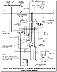
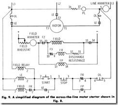
Across-the-Line Starting-Across-the-line starting consists simply of closing the main line switch, either manually or by means of a push-button arrangement in conjunction with a magnetic type of starter or circuit breaker. After synchronous speed has been attained, the field current is applied as previously described. This method of starting should always be adhered to, unless the driven machine requires two or more increments of starting torque or unless the power-system limita tion requires a starting current below that of the full voltage surge. An automatic across-the-line synchronous-motor starting wiring arrange ment is shown in Fig. 8, with its elementary diagram in Fig. 9. The operation and function of the devices shown in Fig. 9 are as follows: Pushing the start button energizes main contactor coil LE, closing the main contacts and connecting L1 , L2 , and L3 to the motor. An interlock ( 1) closes at the same time as the main contactor and forms a holding
circuit so that the push button may be released.
While the motor is accelerating, the field circuit is closed through a normally closed pole, f3, of the field contactor, through the discharge resistor and retarding coil FR of the synchronizing relay. This holds the contacts of the synchronizing relay open until the motor approaches synchronism. At the time the main contactor closes, the contactor coil of the synchronizing relay is energized and tends to close the contacts.
As the motor accelerates, the induced field current through the retarding coil of the synchronizing relay decreases, which releases the interlock when the motor nears synchronism. After a few seconds of delay, the interlock closes, energizing the field-contactor coil, causing F1 and F2 to close and F3 and F4 to open. The closing of F1 and F2 applies excitation to the motor field, completing the starting operation. The opening of F3 opens the discharge circuit of the motor field. Operation of the stop button or the overload relay at any time opens the control circuit and the contactors open, disconnecting the motor from the line.
Some exciters tend to build up voltage slowly. Because of this, the field contactor is equipped with a normally-closed interlock which may be used to short-circuit the exciter-field rheostat, thus causing the exciter voltage to build up more quickly.
Power company rules usually limit the starting current which may be drawn by a motor. There are two types of such rules, one type specifying the allowable number of amperes for each horsepower rating. The more recent “increment” type of rule is based on the capacity to serve a given installation. Usually the total current is not limited, but must be taken in incremental steps, the magnitude of each step being determined by the total connected load.
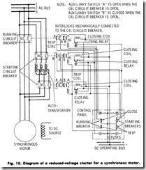
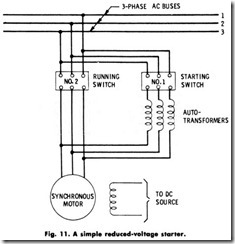
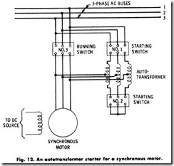
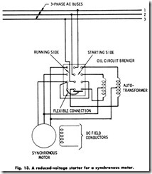
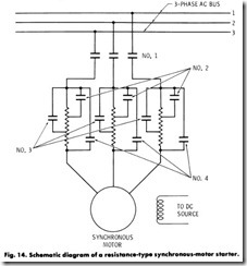
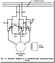
Reduced- Voltage Starting-Reduced-voltage starting differs from the across-the-line method in that reduced voltage is first applied to the motor by means of a transformer (usually an autotransformer). Full voltage is applied only after the motor has reached nearly synchronous speed. Various methods of manual reduced-voltage starting are shown in Figs. 10 to 15.
The starting method shown in Fig. 10 utilizes three switches or contactors. Here, the two starting switches, or contactors, are connected to each side of the autotransformer or compensator and are both closed at the same time. After the motor has attained nearly synchronous speed, the starting switches are opened and the running switch is closed. Most starting arrangements of this type are equipped with electrical or mechanical interlocks in order to prevent any manipulating of the switches, except in the correct sequence.
The starting method shown in Fig. 11 consists of two switches or contactors. Here, the running switch is closed after the motor speed becomes constant, connecting the motor to the line. The starting switch then opens, being interlocked with the running switch. As soon as the speed again becomes constant, the field switch (not shown) is closed. The controller remains in the running position until the running switch is tripped.
Another synchronous-motor starting method is illustrated in Fig. 12. Switches 1 and 2 are first closed, simultaneously connecting the motor to the line through the star-connected autotransformers. Power is then supplied to the motor at a reduced voltage. Switch / is opened as soon as the speed becomes constant, and switch 3 closes instantly, being electrically interlocked with switch/. This connects the motor directly across the line, the terminal voltage having increased to normal without dropping to zero. Switch 2 is interlocked with switch 3 so that it opens immediately after switch 3 closes. The field switch is closed as soon as the speed again becomes constant. The motor is stopped by switch 3, after which the field switch is opened.
A manual synchronous-motor starting method utilizing two circuit breakers enclosed in one tank is shown in Fig. 13. The two autotrans former coils are short-circuited at starting, and the reduced voltage is supplied from the transformer taps as indicated. The autotransformers are usually supplied with several taps in order to provide a suitable range of starting rotque.
Reactance Starting-Reactance starting is similar to the previously discussed reduced-voltage starting methods, except that the first step is obtained by reactance in series with the motor armature instead of autotransformers. In the reactance method of starting, more current is required from the line for the same torque on the first step than when compensators are used. It has an advantage, however, in that no circuit opening is required when the motor is transferred to running voltage, the transfer being accomplished by short-circuiting the reactance.
Resistance Starting-A typical circuit diagram using the resistance method of reduced-voltage starting is shown in Fig. 14. Here, switch 1 is closed first, connecting the motor to the line through the entire resistance. Switches 2, 3, and 4 are then closed, with a time interval between each closing, each switch in turn short -circuiting a part of the resistance. This method of starting is sometimes used when power company rulings require several progressive steps of starting current.
Korndorfer Starting-In common with the reactance and resistance method of starting, the Korndorfer method permits the motor to be started without opening the motor circuit. The motor is first connected through suitable taps of a compensator, and then started by connecting the compensator to the line. Full voltage is connected by first opening the neutral of the starting compensator, allowing the motor to run with part of the compensator winding in series with the motor, and then short-circuiting the entire compensator winding.
With reference to Fig. 15 (showing a typical Korndorfer starting method), switch or contactor 1 is first closed, thus connecting one of the compensator windings to the line. Then switch 2 is closed, completing the motor circuit at reduced voltage. As the motor increases its speed, a timing relay operated by switch 2 opens the circuit of 3, which in turn opens the transformer neutral. Switch 4 is next closed, connecting the motor to full line voltage by short-circuiting the compensator sections. By opening switch 2, the reduced- voltage taps of the compensator are disconnected and the permanent running connection to the motor is completed.
Part- Winding Starting-Part-winding starting is sometimes used on synchronous motors. The motor is equipped with various taps on the armature connected to suitable switches. One arrangement of this sort consists in making a two-circuit armature winding such that one circuit can be used to start the motor while the other is left disconnected. This second-winding is connected after the motor has been accelerated a required amount.
Another method of synchronous-motor starting is to use an auxiliary prime mover, usually an induction motor. This method of starting is applied to motors having no squirrel-cage winding, or to alternators converted to motor use. The motor can carry no mechanical load while starting.
APPLICATION
The correct selection and application of a motor involve a great many factors affecting the installation, operation, and subsequent servicing of the motor. In most cases, the answers to a number of the problems are obvious, while in other instances, the answers are supplied in whole or part by certain intermediaries, such as the manufacturers of motor equipped devices.
The various classes of service for which synchronous motors are used
may be classified as follows:
1. Power-factor correction,
2. Constant-speed, constant-load drives,
3. Voltage regulation.
On power systems employing a large number of induction motors and in other devices having a lagging power factor (such as welders, fluorescent lights, etc), the power factor may be improved by installa tion of devices operating with a leading power factor. Such devices are:
1. Synchronous motors,
2. Synchronous Capacitors.
When synchronous motors are employed exclusively as power factor correction devices, they are termed synchronous capacitors, because the effect on the power system is the same as that of a static capacitor which also produces a leading current. The power factor of a synchro nous motor may be varied by adjustment of the field current. Thus, the power factor may be varied in small steps from a low lagging to a low leading power factor. This makes it possible to vary the power factor over a considerable range and places the characteristics of the motor under the immediate control of the operator at all times.
Because of the higher efficiency possible with synchronous motors, they can be used advantageously on most loads where constant speed is required. Typical applications of high-speed synchronous motors (above 500 r/min) are such drives as centrifugal pumps, de generators, belt-driven reciprocating compressors, fans, blowers, line shafts, cen trifugal compressors, rubber and paper mills, etc.
The field of applications of low-speed synchronous motors (below 500 r/min) are drives such as reciprocating compressors (largest field of use), Jordan engines, centrifugal and screw-type pumps, ball and tube mills, vacuum pumps, electroplating generators, line shafts, rubber and band mills, chippers, metal rolling mills, etc. Synchronous motors are rarely used in sizes below 20 hp (14.92 kW). The principal field of application is in sizes of 100 hp (74.6 kW) and larger.
Another field where synchronous motors are suitable is voltage regulation. At the ends of long transmission lines, the voltage tends to vary greatly, especially if large inductive loads are present. If an inductive load is disconnected suddenly, the voltage may rise consid erably above normal because of the capacity effect or capacitor action of the line. By installing a synchronous motor with a voltage regulator to control its field, the voltage change on the line may be controlled. The action of the voltage regulator is such that when the voltage drops because of an inductive load, the field strength of the synchronous motor is increased. This raises the power factor and maintains the voltage at the same value. If the voltage tends to rise because of the capacity effect of the line, the regulator weakens the field and causes the motor to have a lagging or inductive load so as to hold the voltage to normal.
