Starting of Induction Motors
It has been shown earlier that a plain induction motor is similar in action to a polyphase transformer with a short-circuited rotating secondary. Therefore, if normal supply voltage is applied to the stationary motor, then, as in the case of a transformer, a very large initial current is taken by the primary, at least, for a short while. It would be remembered that exactly similar conditions exist in the case of a d.c. motor, if it is thrown directly across the supply lines, because at the time of starting it, there is no back to oppose the initial inrush of current.
Induction motors, when direct-switched, take five to seven times their full-load current and develop only 1.5 to 2.5 times their full-load torque. This initial excessive current is objectionable because it will produce large line-voltage drop that, in turn, will affect the operation of other electrical equipment connected to the same lines. Hence, it is not advisable to line-start motors of rating above 25 kW to 40 kW.
It was seen in Art. 34.15 that the starting torque of an induction motor can be improved by increasing the resistance of the rotor circuit. This is easily feasible in the case of slip-ring motors but not in the case of squirrel-cage motors. However, in their case, the initial in-rush of current is controlled by applying a reduced voltage to the stator during the starting period, full normal voltage being applied when the motor has run up to speed.
Direct-switching or Line starting of Induction Motors
 Hence, we find that with a current as great as seven times the full-load current, the motor develops a starting torque which is only 1.96 times the full-load value.
Some of the methods for starting induction motors are discussed below :
Squirrel-cage Motors
(a) Primary resistors (or rheostat) or reactors
(b) Auto-transformer (or autostarter)
(c) Star-delta switches
In all these methods, terminal voltage of the squirrel-cage motor is reduced during starting.
Slip-ring Motors
(a) Rotor rheostat
Squirrel-cage Motors
(a) Primary resistors
Their purpose is to drop some voltage and hence reduce the voltage applied across the motor terminals. In this way, the initial current drawn by the motor is reduced. However, it should be noted that whereas current varies directly as the voltage, the torque varies as square of applied voltage*
(a)]. This method can be used both for star-and delta-connected motors. As shown in Fig. 35.20 with starting connections, a reduced voltage is applied across the motor terminals. When the motor has ran up to say, 80% of its normal speed, connections are so changed that auto-transformers are cut out and full supply voltage is applied across the motor. The switch making these changes from ‘start’ to ‘run’ may be airbreak (for small motors) or may be oil-immersed (for large motors) to reduce sparking. There is also provision for no-voltage and over-load protection, along with a time-delay device, so that momentary interruption of voltage or momentary over-load do not disconnect the motor from supply line. Most of the auto-starters are provided with 3 sets of taps, so as to reduce voltage to 80, 65 or 50 per cent of the line voltage, to suit the local conditions of supply. The V -connected auto-transformer is commonly used, because it is cheaper, although the currents are unbalanced during starting period. This is, however, not much objectionable firstly, because the current imbalance is about 15 per cent and secondly, because balance is restored as soon as running conditions are attained.
The quantitative relationships between the motor current, line current, and torque developed can be understood from Fig.35.20.
In Fig 35.20 (a) is shown the case when the motor is direct-switched to lines. The motor current is, say, 5 times the full-load current. If V is the line voltage, then voltage/phase across motor is V / 3 .
The current taken from supply or by auto-transformer is I1 = K I2 = K Isc if magnetising current of the transformer is ignored. Hence, we find that although motor current per phase is reduced only K times the direct-switching current (∵ K < 1), the current taken by the line is reduced K2 times.
Now, remembering that torque is proportional to the square of the voltage, we get
Tutorial Problems
1. A 3-f motor is designed to run at 5% slip on full-load. If motor draws 6 times the full-load current at starting at the rated voltage, estimate the ratio of starting torque to the full-load torque.
[1.8] (Electrical Engineering Grad, I.E.T.E. Dec. 1986)
2. A squirrel-cage induction motor has a short-circuit current of 4 times the full-load value and has a full-load slip of 5%. Determine a suitable auto-transformer ratio if the supply line current is not to
exceed twice the full-load current. Also, express the starting torque in terms of the full-load torque. Neglect magnetising current.
[70.7%, 0.4]
3. A 3-f, 400-V, 50-Hz induction motor takes 4 times the full-load current and develops twice the full- load torque when direct-switched to 400-V supply. Calculate in terms of full-load values (a) the line current, the motor current and starting torque when started by an auto-starter with 50% tap and (b) the voltage that has to be applied and the motor current, if it is desired to obtain full-load torque on starting. [(a) 100%, 200%, 50% (b) 228 V, 282%]
(c) Star-delta Starter
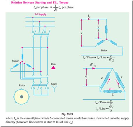
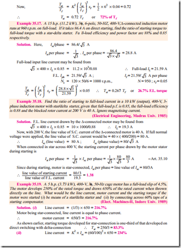
This method is used in the case of motors which are built to run normally with a delta-connected stator winding. It consists of a two-way switch which connects the motor in star for starting and then in delta for normal running. The usual connections are shown in Fig. 35.21. When star-connected, the applied voltage over each motor phase is reduced by a factor of 1/ 3 and hence the torque developed becomes 1/3 of that which would have been developed if motor were directly connected in delta. The line current is reduced to 1/3. Hence, during starting period when motor is Y -connected, it takes 1/3rd as much starting current and develops 1/3rd as much torque as would have been developed were it directly connected in delta.
Tutorial Problems 35.3
1. A 3-phase induction motor whose full-load slip is 4 per cent, takes six times full-load current when switched directly on to the supply. Calculate the approximate starting torque in terms of the full-load torque when started by means of an auto-transformer starter, having a 70 percent voltage tap.
[0.7 Tf ]
2. A 3-phase, cage induction motor takes a starting current at normal voltage of 5 times the full-load value and its full-load slip is 4 per cent. What auto-transformer ratio would enable the motor to be started with not more than twice full-load current drawn from the supply ?
What would be the starting torque under these conditions and how would it compare with that obtained by using a stator resistance starter under the same limitations of line current ?
[63.3% tap ; 0.4 Tf ; 0.16 Tf ]
3. A 3-phase, 4-pole, 50-Hz induction motor takes 40 A at a full-load speed of 1440 r.p.m. and develops a torque of 100 N-m at full-load. The starting current at rated voltage is 200 A. What is the starting torque ? If a star-delta starter is used, what is the starting torque and starting current ? Neglect magnetising current.
[100 N-m; 33.3 N-m; 66.7 A] (Electrical Machines-IV, Bangalore Univ. Aug. 1978)
4. Determine approximately the starting torque of an induction motor in terms of full-load torque when started by means of (a) a star-delta switch (b) an auto-transformer with 50% tapping. Ignore magnetising current. The short-circuit current of the motor at normal voltage is 5 times the full-load current and the full-load slip is 4 per cent.
[(a) 0.33 (b) 0.25] (A.C. Machines, Madras Univ. 1976)
5. Find the ratio of starting to full-load current for a 7.46 kW, 400-V, 3-phase induction motor with star/ delta starter, given that the full-load efficiency is 0.87, the full-load p.f. is 0.85 and the short-circuit current is 15 A at 100 V.
[1.37] (Electric Machinery-II, Madras Univ. April 1978)
6. A four-pole, 3-phase, 50-Hz, induction motor has a starting current which is 5 times its full-load current when directly switched on. What will be the percentage reduction in starting torque if (a) star-delta switch is used for starting (b) auto-transformer with a 60 per cent tapping is used for starting ?
(Electrical Technology-III, Gwalior Univ. Nov. 1917)
7. Explain how the performance of induction motor can be predicted by circle diagram. Draw the circle diagram for a 3-phase, mesh-connected, 22.38 kW, 500-V, 4-pole, 50-Hz induction motor. The data below give the measurements of line current, voltage and reading of two wattmeters connected to measure the input :


