capacitors
Four factors affect the capacitance of a capacitor:
1. Area of the plate
2. Distance between the plates
3. Type of dielectric material
4. Temperature
A capacitor is either fixed or variable. A fixed capacitor has a definite value that cannot be changed. A variable capacitor is one whose capacitance can be changed either by varying the space between plates (trimmer capacitor) or by varying the amount of meshing between two sets of plates (tuning capacitor).
Capacitance is directly proportional to the area of the plate. For example, doubling the plate area doubles the capacitance if all other factors remain the same.
Capacitance is inversely proportional to the distance between the plates. In other words, as the plates move apart, the strength of the electric field between the plates decreases.
The ability of a capacitor to store electrical energy depends on the electrostatic field between the plates and the distortion of the orbits of the electrons in the dielectric material. The degree of distortion depends on the nature of dielectric material and is indicated by its dielectric constant. A dielectric constant is a measure of the effectiveness of a material as an insula- tor. The constant compares the material’s ability to dis- tort and store energy in an electric field to the ability of air, which has a dielectric constant of 1. Paper has a dielectric constant of 2 to 3; mica has a dielectric constant of 5 to 6; and titanium has a dielectric constant of 90 to 170.
The temperature of a capacitor is the least significant of the four factors. It need not be considered for most general-purpose applications.
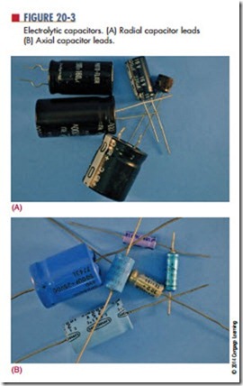
Capacitors come in many types and styles to meet the needs of the electronics industry. electrolytic capacitors offer large capacitance for small size and weight (Figure 20-3). Electrolytic capacitors consist of two metal foils separated by fine gauze or other absorbent material that is saturated with a chemical paste called an electrolyte. The electrolyte is a good conductor and serves as part of the negative plate. The dielectric is formed by oxidation of the positive plate. The oxidized layer is thin and a good insulator. An electro- lytic capacitor is polarized, having positive and negative leads. Polarity must be observed when connecting an electrolytic capacitor in a circuit.
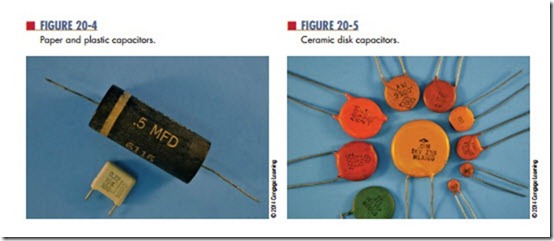
Paper capacitors and plastic capacitors are constructed by a rolled foil technique (Figure 20-4). A paper dielectric has less resistance than a plastic film
dielectric, and plastic film is now being used more as a result. The plastic film allows a metallized film to be deposited directly on it. This reduces the distance between plates and produces a smaller capacitor.
The ceramic disk capacitor is popular because it is inexpensive to produce (Figure 20-5). It is used for capacitors of 0.1 microfarad and smaller. The ceramic material is the dielectric. This is a tough, reliable, general-purpose capacitor.
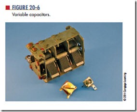
Variable capacitors also come in all sizes and shapes (Figure 20-6). Types include padders, trimmers, and tuning capacitors. Padder and trimmer capacitors must be adjusted by a technician. The user can adjust tuning capacitors.
Like resistors and inductors, capacitors can be connected in series, parallel, and series-parallel combinations. Placing capacitors in series effectively increases the thickness of the dielectric. This decreases the total capacitance, because capacitance is inversely proportional to the distance between the plates. The total capacitance of capacitors in series is calculated like the total resistance of parallel resistors
![]() When capacitors of different values are connected in series, the smaller capacitors charge up to the highest voltage. Placing capacitors in parallel effectively adds to the plate area. This makes the total capacitance equal to the sum of the individual capacitances:
When capacitors of different values are connected in series, the smaller capacitors charge up to the highest voltage. Placing capacitors in parallel effectively adds to the plate area. This makes the total capacitance equal to the sum of the individual capacitances:
CT = C1 + C2 + C3 . . . +Cn
Capacitors in parallel all charge to the same voltage
Questions
1. What four factors affect capacitance?
2. What are the advantages of electrolytic
capacitors?
3. What are other names for variable capacitors?
4. What is the formula for total capacitance in series circuits?
What is the formula for total capacitance in parallel circuits?


