All digital equipment, whether simple or com- plex, is constructed of only a few basic circuits. These circuits, referred to as logic elements, perform some logic function on binary data.
There are two basic types of logic circuits: decision- making and memory. Decision-making logic circuits monitor binary inputs and produce an output based on the status of the inputs and the characteristics of the logic circuit. Memory circuits are used to store bi- nary data.
AND Gate
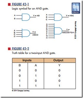
The AND gate is a logic circuit that has two or more inputs and a single output. The AND gate produces an output of 1, only when all its inputs are 1s. If any of the inputs are 0s, the output is 0.
Figure 42-1 shows the standard symbol used for AND gates. An AND gate can have any number of in- puts greater than one. Shown in the figure are symbols representing the more commonly used gates of two, three, four, and eight inputs.
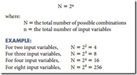
The operation of the AND gate is summarized by the table in Figure 42-2. Such a table, called a truth table, shows the output for each possible input. The
inputs are designated A and B. The output is designated Y. The total number of possible combinations in the truth table is determined by the following formula:
The AND gate uses the rules of multiplication. The AND function is known for multiplication-like results. The output of an AND gate is represented by the equa- tion Y 5 A·B or Y 5 AB. The AND function is typically represented by the two variables A and B as AB.
Questions
1. under what conditions does an AND gate produce a 1 output?
2. Draw the symbol used to represent a two-input AND gate.
3. Develop a truth table for a three-input AND gate.
4. What logical operation is performed by an AND gate?
5. What is the algebraic output of an AND gate?

