Objectives
After studying this unit, the student will be able to:
• Identify terminal markings for a star-delta motor and motor starter
• Describe the purpose and function of star-delta starting
• Troubleshoot star-delta motor starters
• Connect star-delta motors and starters
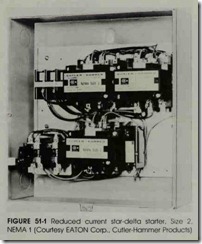
A commonly used means of reducing inrush currents without the need of external devices is star-delta motor starting (sometimes called wye delta starting). Figure 51-1 shows a typical star delta starter.
Star-delta motors are similar in construction to standard squirrel cage motors. However, in star-delta motors, both ends of each of the three windings are brought out to the terminals. If the starter used has the required number of properly wired contacts, the motor can be started in star and run in delta.
The motor must be wound in such a manner that it will run with its stator windings connected delta. The leads of all of the windings must be Ibrought out to the motor terminals for their
proper connection in the field
APPLICATIONS
The primary applications of star-delta motors are for driving centrifugal chillers of large, central air conditioning units for loads such as fans, blow ers, pumps, or centrifuges, and for situations
where a reduced starting torque is necessary. Star delta motors also may be used where a reduced starting current is required. Since all of the stator winding is used and there are no limiting devices such as resistors or autotransformers, star-delta motors are widely used on loads having high iner tia and a long acceleration period.
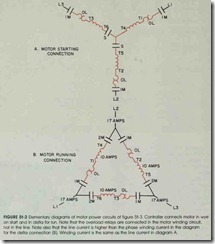
The speed of a star-delta, squirrel cage induc tion motor depends upon the number of poles of the motor and the supply line frequency (hertz). Since both of these values are constant, the motor will run at approximately the same speed for ei ther the star or delta connection. The inrush and line current are less when the motor is connected star than when it is connected in delta. The winding current is less than the line current when the motor is connected in delta. That is, the in rush and line current in the star connection are one-third the values of these quantities in the delta connection. The winding current in star is 1.73 times the winding current in delta.
OVERLOAD PROTECTION SELECTION
Three overload relays are furnished on star delta starters. These relays are wired so that they carry the motor winding current, figure 51-2. This means that the relay units must be selected on the basis of the winding current, not the delta-con nected full load current. If the motor nameplate indicates only the delta-connected full load current, divide this value by 1.73 to obtain the wind ing current which is used as the basis for selecting the motor winding protection.
OPERATION
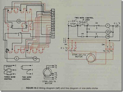
Open transition starting for a star-delta starter is shown in figure 51-3. As indicated in the line diagram on the right, the automatic transfer from star to delta is accomplished by a pneumatic timer. The timer is operated by the movement of the armature of one of the contactors. Operating the push-button station start button energizes con tactor S. The main contacts of contactor S connect three of the motor leads together (T4, T5, and T6) to form a star. About the same time, the normally open, control contact (S) of the same contactor energizes another contactor (1M) and m intains it self. Since the pneumatic timer is attached to con tactor 1M, the motor is connected to the line in star and the timing period is started . When the timing period is complete, the first contactor (S) is de-energized. As a result , normally closed inter lock S is closed , and contactor 2M is energized to connect the motor in delta. The motor then runs in the delta-connected configuration. This start run scheme is called open transition because there is a movement in which the motor circuit is open between the opening of the power contacts (S) and the closing of the contacts (2M).
CLOSED TRANSITION STARTING
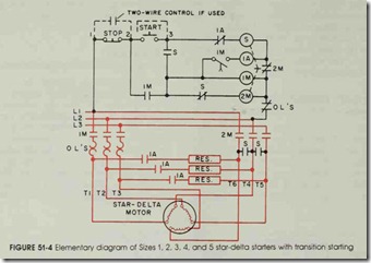
Figure 51-4 shows a modification of figure 51-3. In figure 51-4, resistors maintain continuity to the motor to avoid the difficulties associated with the open circuit form of transition between start and run.
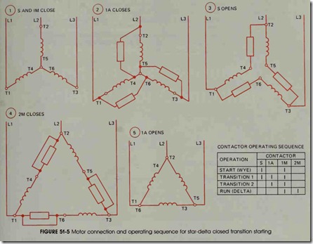
With closed transition starting, the transfer from the star to delta connections is made without disconnecting the motor from the line. When the transfer from star to delta is made in open transi tion starting, the starter momentarily disconnects the motor and then reconnects it in delta. While an open transition is satisfactory in many cases, some installations may require closed transition starting to prevent power line disturbances. Closed transition starting is achieved by adding a three-pole contactor and three resistors to the starter circuit. The connections are made as shown in the closed transition schematic diagram, figure 51-4. The contactor is energized only during the transition from star to delta. It keeps the motor connected to the power source through the resis tors during the transition period, figure 51-5. There is a reduction in the incremental current surge which results from the transition. The bal ance of the operating sequence of the closed tran sition starter is similar to that of the open transi tion star-delta motor starter.
A single method of reduced current starting may not achieve the desired results because the motor starting requirements are so involved, the restrictions so stringent, and the needs so conflicting. It may be necessary to use a combination of starting methods before satisfactory performance is realized. For special installations, it may be neeessary to design a starting system to fit the partic ular conditions.
REVIEW QUESTIONS
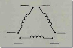
1. Indicate the correct terminal markings for a star-delta motor on the diagram below.
2. What is the principal reason for using star-delta motors?
3. In figure 51-4, which contactor closes the transition?
4. The closed transition contactor is energized only on transfer from star to delta.
How is this accomplished?
5. If a delta-connected, six-lead motor nameplate reads “Full Load Current 170 Amperes,” upon what current rating should the overload relay setting, or the selection of the heater elements be based?
