Root Mean Square Measurements
Figure 1.20(a) shows that, according to Ohm’s law, the power dissipated in a resistance is proportional to the square of the applied voltage. This causes no difficulty with direct current (DC), but with alternating signals such as audio it is harder to calculate the power. Consequently, a unit of voltage for alternating signals was devised. Figure 1.20(b) shows that the average power delivered during a cycle must be proportional to the mean of the square of the applied voltage. Since power is proportional to the square of applied
voltage, the same power would be dissipated by a DC voltage whose value was equal to the square root of the mean of the square of the AC voltage. Thus the volt rms was specified. An AC signal of a given number of volts rms will dissipate exactly the same amount of power in a given resistor as the same number of volts DC.
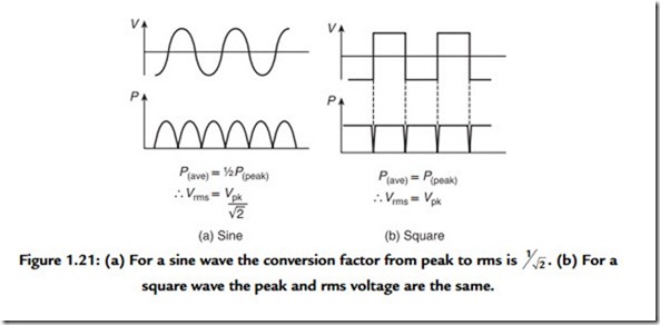
Figure 1.21(a) shows that for a sine wave the rms voltage is obtained by dividing the peak voltage Vpk by the square root of 2. However, for a square wave [Figure 1.21(b)] the rms voltage and the peak voltage are the same. Most moving coil AC voltmeters only read correctly on sine waves, whereas many electronic meters incorporate a true rms calculation.
On an oscilloscope it is often easier to measure the peak-to-peak voltage, which is twice the peak voltage. The rms voltage cannot be measured directly on an oscilloscope since it depends on the waveform, although the calculation is simple in the case of a sine wave.
