SPEAKER BAFFLES AND ENCLOSURES
An essential part of any loudspeaker system is the enclosure in which the loudspeaker is to be used, often called a baffle. The enclosure provides the proper acoustic circuit for the loudspeaker to ensure maximum efficiency and best performance. The sound coming from the loudspeaker is routed into certain paths and prevented from going into other paths by blank walls put in its way. Thus baffle connotes routing the sound energy. Most of baffles today are built into more or less complex box like structures; hence baffles and enclosures are used interchangeably.
ACOUSTIC DOUBLETS
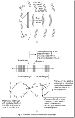
The cone of a loudspeaker moves as a unit. When the cone moves forward, the air in front is compressed and the air in the back of the cone is rarefied. The sound released from the rear of the cone is of opposite phase to that released from the front of the cone. If the sound from the rear is allowed to flow so that it meets the sound from the front, cancellation takes place and the response of the speaker drops off sharply.
Such an arrangement, Fig. 5.1, is called an acoustic doublet in which the two sides of the diaphragm are represented by a negative and a positive pole radiating respectively a negative and a positive wave [see Fig. 5.1 (b)]. If these doublet sources are close together, it is obvious that the negative wave will be cancelled by the positive wave at almost all points in space. This is true, however, if the poles of the doublet are so close that their spacing is only a small fraction of the length of the radiated wave. This condition is readily recognised in any speaker when tested on a workbench without benefit of any baffle at all. Under this condition, the doublet mode of operation is most effectively working, with the result that there is a complete absence of low-frequency response. To prevent low-frequency cancellation resulting from doublet operation, we should place some barrier between the front and the back.
The wavelength of sound becomes longer as the frequency decreases. Front-to-back interference is worst at the lowest frequencies and ordinarily marks the cut off frequency of the speaker mounting. At higher frequencies, the compressions and rarefactions are so closely spaced that there is no definite general cancellation action at the low frequencies.
BAFFLES
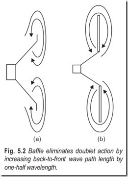
The edges of the cone can be extended with some rigid flat material, so that it is necessary for sound waves from the rear to travel out to the edges of the material before they can meet the sound waves from the front and interfere with them. The added material is called, a baffle, and its principle is illustrated in Fig. 5.2.
With the speaker alone, Fig. 5.2 (a), the front and rear waves must travel only along one side of the cone to meet at the edge. This path is so short that a speaker alone without baffle will usually not reproduce much below about 350 Hz. Fig 5.2 (b) shows the situation with a baffle added. The length of the interference path is increased by the width of the baffle material on each side of the cone.
Baffles should be made of good sound insulating material and should be soft enough to prevent rattling. Soft woods are satisfactory but a material like Celotex is more appropriate. The speaker must be securely fastened to the baffle, and the baffle must be rigidly mounted to prevent rattling.
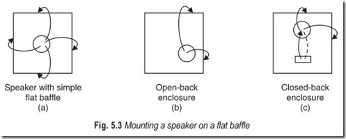
If a baffle is to be of limited size, the speaker should not be mounted in the centre. The centre is a bad position because the path lengths to all four edges are the same and the frequency components, on one side, at which the path length is one wavelength are severely attenuated, Fig. 5.3 (a). If the speaker is moved towards one corner, Fig. 5.3 (b), the uniformity of response is much better because the path length to each edge is different and the interference attenuation is distributed. The interference does not have to take place around the edge of the baffle, but sometimes is deliberately made to take place through a port, as illustrated in Fig 5.3 (c). The design principle of such an arrangement is to equalise the response peak due to speaker resonance by the sharp attenuation around that frequency by spacing the port so that the sound travels a half wavelength.
INFINITE BAFFLE SYSTEMS
An infinite baffle, or an approximation of it, is one of the best speaker mountings. However, its size is a disadvantage in an ordinary home. Because of the size problem, various arrangements have been developed in an attempt to get the same effect without the use of so much space. This has led to the design of speaker enclosures.
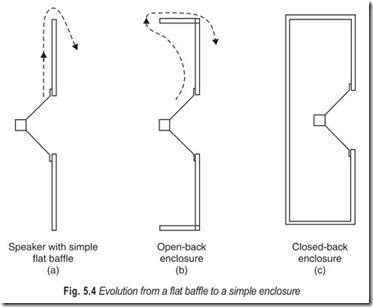
A true infinite baffle completely eliminates doublet action. The complete absence of doublet operation will ensure that the low-frequency response obtained will be limited not only by the baffle, but by the low-frequency capabilities of the loudspeaker used in the installation. The evolution from a flat baffle to a simple enclosure is illustrated in Fig. 5.4. The simple flat baffle is shown in Fig. 5.4 (a). To reduce the maximum dimension of the baffle, the outer portions can be bent back at the four edges to form an open box, Fig. 5.4 (b). The path length is as great as for the flat versions, but the lateral dimensions are smaller. In Fig. 5.4 (c) the process is carried one step further, and the back of the enclosure is enclosed, the back prevents any sound from the rear from getting to the front.
The open-back cabinet arrangement of Fig. 5.4 (b) is the one commonly employed for radio and television receivers. The low-frequency response is lacking in this type of arrangement. The small speaker used and the cabinet are limiting factors. Large console models employ larger speakers and larger cabinets, but the path length is seldom sufficient to allow reproduction below 150 Hz, unless some special cabinet design is used.
The open-back box speaker has yet another disadvantage. Any sudden sound peaks of any frequency, or sounds of low-frequency, can shock-excite the box into oscillation at the resonant frequency. This accounts for the fact that many console radio receivers and some of the earlier juke boxes emitted a constant booming sound during reproduction of music.
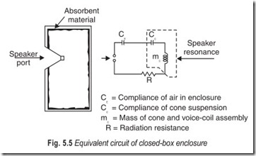
As soon as the box is closed as in Fig. 5.4 (c), the air in it is no longer free to move in the open as in the open-back cabinet. Instead the action of the cone causes pressure changes in the cabinet rather than combination of pressure and velocity. This means that the compliance of air is an important factor. Compliance is acoustic capacitance and combines with the compliance of the cone suspension in such a way as to raise the resonant frequency of the system to a value higher than that of the speaker alone.
The mass (inductive effect) of the cone, the compliance (capacitive effect) of the cone suspension, and the compliance (capacitive effect) of the air in the box are all effectively in series with each other, Fig. 5.5. An important feature of the closed box is the fact that, because there is no motion of air in and out of it, there is no inertance or inductive effect. There is only compliance, or capacitive effect. Accordingly, the box does not resonate but enter the resonant circuit of the speaker unit and raise the resonant frequency of the system above that of the speaker. Generally, a closed box of a given volume will raise the resonant frequency of the system by a given percentage above the resonant frequency of the speaker.
Because the closed box keeps back radiation from getting around to the front and interfering, it is frequently referred to as the infinite baffle. The closed box enclosure is not at all equivalent to a true infinite baffle unless it is so large that its effect on the resonant frequency is negligible.
In the infinite-baffle enclosure, all radiation from the rear of the speaker is eliminated. This minimises interference but also makes systems of this type less efficient than others which utilise the sound from the rear.
One way to overcome this loss of efficiency is to use two or more identical speakers in the enclosure. When two or more speakers operate on the same audio frequency and are mounted close to each other, they interact. Sound energy from one speaker reinforces the vibration of the cone of the other speaker and vice versa, in what is known as mutual coupling. The action is similar to that in a multielement antenna array. The result is that the efficiency of the combination is much better than the efficiency of either speaker alone.
Even speakers of the same model are seldom exactly alike, because of tolerances in manufacture. These tolerances are actually an advantage because the difference in the resonant frequencies of the respective speakers tends to distribute the speaker resonance effect and make low-frequency response more uniform.
BASS-REFLEX SYSTEMS
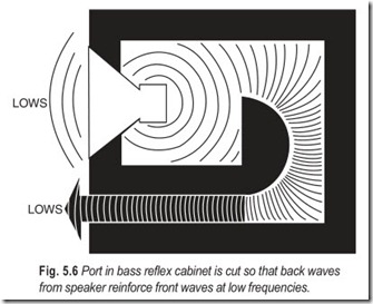
In another, more popular arrangement, radiation from the rear of the cone is used to reinforce the front radiation rather than cancel it. This arrangement is shown in Fig. 5.6, and is known as the bass-reflex enclosure. It is the same as the closed box except that an opening is cut below the speaker. Which allows air to flow in and out of the box as the speaker cone moves back and forth.
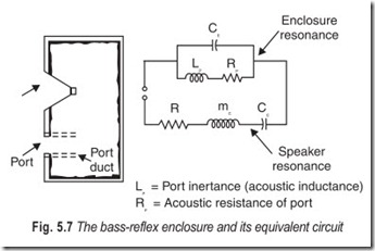
Addition of the port adds acoustic inductance (inertance) to the load offered to the speaker by the cabinet, because of the motion of air through the port. The flow of air through the port is also accompanied by friction, which is an acoustic resistance effect. The port inertance, friction, and enclosure compliance form a parallel-resonant circuit, Fig. 5.7. This circuit is connected effectively in series with the series – resonant circuit of the suspension and mass of the cone of the speaker.
The effective length of the path of the sound from the rear of the cone is primarily dependent on the nature of the impedance offered by the enclosure itself, as expressed in the equivalent circuit. The design is simply a matter of keeping the resonant frequency of the enclosure in proper relation to the resonant frequency
of the speaker. Because the enclosure offers parallel resonance, and the speaker series resonance, one of these resonances can be made to offset the other.
Because the bass-reflex enclosure reverses the phase of the back radiation and makes it additive to the front radiation at low-frequencies, it is often referred to as an acoustic phase inverter.
Some designers prefer to make the bass-reflex type of enclosure with distributed ports. Instead of one port of calculated size, a number of smaller ports are used. The areas of distributed ports add up to the proper calculated port area.
ACOUSTIC LABYRINTH SYSTEMS
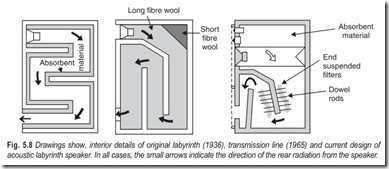
The labyrinth is a tuned pipe with one open end. When the wave from the speaker reaches the end of the pipe, it spreads out into the listening environment causing a sudden pressure drop which reflects back through the pipe to the speaker as a rarefaction. At the quarter wave frequency (l/4) of the sound, the air in the mouth of the pipe is at minimum velocity but maximum pressure (Bernoulli’s theorem). This condition produces an accompanying maximum rarefaction reflected back to the speaker cone. Here, the antiresonant action of the pipe offers maximum damping to the speaker (See Fig. 5.8 and 5.9).
The frequency at which the length of the pipe is a half-wavelength (l/2) of the sound, the air in the mouth is at low pressure but high velocity. Because there is no sudden change in pressure as the wave moves out of the pipe, there is no antiresonant action by the pipe, and the speaker cone is able to move freely. And, because of the l/2 phase shift (180°) within the pipe, the emerging wave is in-phase with that coming from the front of the cone, adding to the speaker’s output.
The Olney labyrinth (1936) utilised a pipe cut to l/4 at the speaker’s resonant frequency. The l/4 action of the pipe damped the speaker’s resonance, reducing boom; the l/2 action added to the speaker’s output in the octave above resonance. Olney chose the l/2 frequency to be about 75 Hz. His 8″ speaker had a 50 Hz free-air resonance reduced to 40 Hz by the labyrinth. Olney noted the presence of objectionable resonances, which were produced as harmonics of the fundamental resonance of the enclosure. To counter this he lined the walls with sound absorbing material which combined with bends in the pipe, eliminated the output from the labyrinth at frequencies greater than 150 Hz.
Bailey developed stuffed transmission line (1965). The theory behind it is that an infinitely long acoustic line, or pipe, will absorb the back wave from the speaker without troublesome reflections that can produce standing waves behind the cone. A line of infinite length, of course, would be impractical; so, Bailey substituted stuffing for length. His long-fibre wood stuffing attenuated the back wave so effectively that the sudden pressure changes at the mouth, with their attendant reflections, were avoided. Extremely low-frequencies were not attenuated and escaped to increase bass response. Bailey claimed, that his transmission line, with its less abrupt low-end cutoff, produced less ringing than conventional ported enclosures.
The current design uses a tapered pipe with variable density damping. This transmission line damps three resonances—air in the top chamber resonating with the mass and compliance of the driver tube resonance, and free air resonance of the driver—thus broadening and extending the bandpass.
FOLDED-HORN SYSTEMS
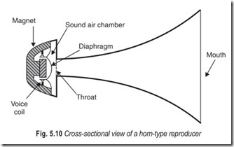
Outdoor speaker systems and many movie theatre sound systems employ speaker coupling systems known as exponential horns. Such horns with their constant rate of flare provide an acoustical match between the cone of the loudspeaker and the air to which sound energy must be coupled (See Fig. 5.10).
To effective horns make, it must be designed to a length that is determined by the lowest cutoff frequency desired. For example, to be able to use a horn design down to 32 Hz the horn would have to be nearly 9 ft. long. Even the average listening room would not accommodate one of these. Nevertheless, horn designs provide by far the greatest speaker efficiency attainable among the systems discussed. Fundamental horns are often used in tweeter or high-frequency arrays in multi-element speaker system designs.
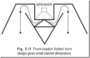
For use at lower frequencies, many manufacturers have evolved variations of the horn principle called the folded horn design. A cross-sectional view of such a design is shown in Fig. 5.11. In this folded configuration, the design lends itself to more acceptable furniture concepts in speaker enclosures. Well-designed systems based upon the folded-horn principle are quite popular because of the vast amounts of sound they can produce for a given amount of amplifier driving power.
CORNER FOLDED HORN SYSTEMS
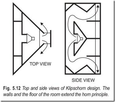
Shown in Fig. 5.12 are top and side cross-sectional views of the most enduring horn design—the Klipschorn—invented and patented by Paul W. Klipsch.
The enclosure is a low-frequency horn so folded that it can be placed in the corner of a room to utilise reflections from the floor and walls to improve the impedance match at the mouth of the horn and thereby increase response at low-frequencies. It is as though the walls and floor act as extensions of the horn itself.
A horn of this design offers efficiency that can be 10 to 50 times as great as that offered by an infinite- baffle design ; and therefore, a given amount of acoustic power can be generated with much less excursion of the speaker cone. This often significantly reduces harmonic and intermodulation distortion.
EXERCISES
Descriptive Questions
1. What is the need for a baffle?
2. Explain briefly the different types of baffles.
3. How infinite baffles were evolved?
4. Differentiate between an open-box and a closed-box enclosure.
5. What is an acoustic doublet? Explain the doublet mode of operation. How can doublet action be eliminated?
6. Discuss the action of an infinite baffle. How can an enclosure act as infinite baffle?
7. Explain the working of an acoustic labyrinth system with the help of a neat diagram.
8. Compare a folded horn system with a corner-folded horn system.
9. Draw and explain the equivalent circuit of a closed-box enclosure.
10. Explain the following :
(a) Acoustic phase inverter (b) Distribute ports
Multiple Choice Questions
1. Acoustic doublet action can be prevented by using
(a) a baffle (b) an enclosure
(c) acoustic coupling (d) none of these
2. If a baffle is to be of limited size, the speaker should not be mounted in the
(a) corners (b) centre
(c) either (a) or (b) (d) neither (a) nor (b)
3. A true infinite baffle completely eliminates
(a) speaker resonance (b) doublet action
(c) acoustic coupling (d) none of these
4. Many console radio receivers and some of the early juke boxes emitted a constant.
(a) booming sound (b) metallic sound
(c) wavering sound (d) none of these
5. Compliance is
(a) acoustic capacitance (b) acoustic inductance
(c) acoustic resistance (d) none of these
6. An infinite baffle is
(a) one of the worst speaker mountings (b) one of the best speaker mountings
(c) an ideal speaker mounting (d) an economical speaker mounting
7. Sometimes interference is deliberately made to take place through a
(a) cone (b) horn
(c) baffle (d) port
8. One way to overcome the loss of efficiency is to use
(a) a woofer and a tweeter in the enclosure
(b) two woofers in the enclosure
(c) two tweeters in the enclosure
(d) two identical speakers in the enclosure
9. A bass reflex enclosure is often referred to as
(a) an acoustic lens (b) a series tuned circuit
(c) an acoustic phase inverter (d) a parallel tuned circuit
10. The current design of labyrinth systems uses a
(a) tapered pipe with variable density damping
(b) a cylindrical pipe with variable density damping
(c) a tapered pipe with constant density
(d) a cylindrical pipe with constant density
Fill in the Blanks
1. In an acoustic doublet mode of operation, there is a complete absence of ………………………………………. response.
2. In a closed-box enclosure there is only ………………………………………. effect.
3. The low-frequency response is lacking in………………………………………. cabinet arrangements.
4. In a bass reflex enclosure, radiation from the rear of the cone is used to ………………………………………. the front radiation.
5. Horn designs provide the………………………………………. speaker efficiency.
6. In a corner-folded horn system the walls and the floor act as ………………………………………. of the horn itself.
ANSWERS
Multiple Choice Questions
|
1. (a) |
2. (b) |
3. (b) |
4. (a) |
5. (a) |
6. (b) |
|
7. (d) |
8. (d) |
9. (c) |
10. (a) |
Fill in the Blanks |
||
|
1. low frequency 4. reinforce |
2. capacitive 5. maximum |
3. open 6. extensions |
