OPTICAL RECORDING AND REPRODUCTION
Compact disc (CD) players are a very specialised form of phonograph, record player, or turnable. A CD player plays pre-recorded discs (carrying music, speech, etc.) through a conventional hi-fi or stereo system (amplifier and loudspeakers). The disc is single-sided, 4.75 in (120 mm) in diameter, and can contain upto 60 min of hi-fi stereo sound. The compact disc spins at a high rate of speed compared with a conventional audio record, and uses a light beam/optical pick-up instead of the standard stylus/needle pick-up arm. In addition to superior sound can provide immediate access to audio at any part of the disc. It is also possible to program CD players to play only selected portions of the audio material.
DISC
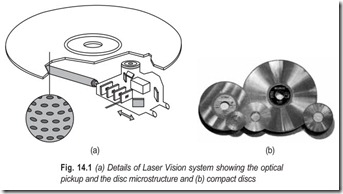
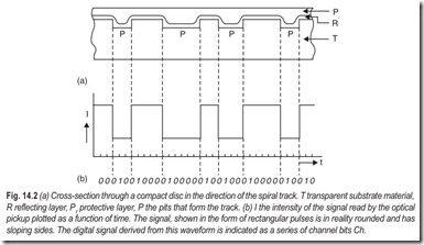
In the Laser Vision System, Fig. 14.1 (a), which records video information, the signal is recorded on the disc in the form of a spiral track that consists of a succession of pits. The intervals between the pits are known as lands. The information is present in the track in analog form. Each transition from land to pit and vice versa marks a zero crossing of the modulated video signal. On the compact disc, Fig. 14.1 (b), the signal is recorded in a similar manner, but the information is present in the track in digital form. Each pit and each land represents a series of bits called channel bits. After each land/pit or pit/land transition there is a 1, and all the channel bits in between are 0, (see Fig. 14.2).
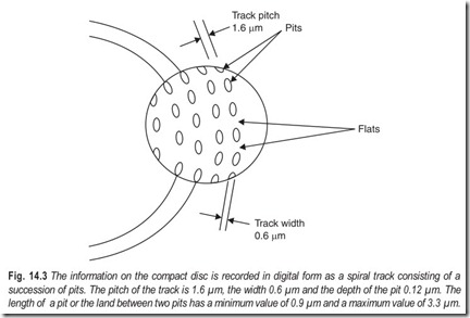
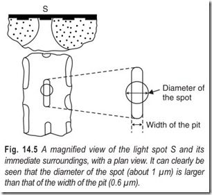
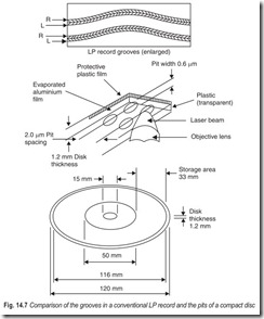
The density of the information on the compact disc is very high; the smallest unit of audio information (the audio bit) covers an area of 1 µm2 on the disc, and the diameter of the scanning light spot is only 1 µm. The pitch of the track is 1.6 µm, the width 0.6 µm and the depth 0.12 µm. The minimum length of a pit or the land between two pits is 0.9 µm, the maximum length is 3.3 µm. The side of the transparent carrier material T in which the pits P are impressed, the upper side during playback if the spindle is vertical, is covered with a reflecting layer R and a protective layer Pr . The track is optically scanned from below the disc at a constant velocity of 1.25 m/s. The speed of rotation of the disc therefore varies from about 8 rev/s to about 3.5 rev/s (or 480 rpm to about 210 rpm).
PROCESSING OF THE AUDIO SIGNAL
For converting the analog signal from the microphone into a digital signal, pulse-code modulation (PCM) is used. In this system the signal is periodically sampled and each sample is translated into a binary number. From Nyquist’s sampling theorem the frequency of the sampling should be at least twice as high as the highest frequency to be accounted for in the analog signal. The number of bits per sample determines the signal-to-noise ratio in the subsequent reproduction.
In the compact disc system the analog system is sampled at a rate of 44.1 kHz, which is sufficient for the reproduction of the maximum frequency of 20 kHz. The signal is quantized by the method of uniform or linear quantization, the sampled amplitude is divided into equal parts. The number of bits per sample (these are called audio bits) is 32 ; i.e. 16 for the left and 16 for the right audio channel. This corresponds to a signal-to-noise ratio of more than 90 dB. The net bit rate is thus 44.1 × 103 × 32 or 1.41 × 10⁶ audio bits per second. The audio bits are grouped into frames, each containing six of the original samples.
Successive blocks of audio bits have blocks of parity bits added to them in accordance with a coding system called Cross-Interleaved Reed-Solomon Code (CIRC). This makes it possible to correct errors during the reproduction of the signal. The ratio of the number of bits before and after this operation is 3 : 4. Each frame then has Control and Display (C & D) bits added to it; one of the functions of C & D bits is providing the information for the listener. After this operation the bits are called data bits.
Next, the bit stream is modulated, that is to say the data bits are translated into channel bits which are suitable for storage on the disc, (see Fig. 14.2 b). The Eight-to-Fourteen Modulation (EFM) is used for this purpose. In EFM code blocks of eight bits are translated into blocks of fourteen bits. The blocks of fourteen bits are linked by these merging bits. The ratio of the number of bits before and after modulation is thus 8 : 17.
For the synchronisation of the bit stream an identical synchronisation pattern consisting of 27 channel bits is added to each frame. The total bit rate after all these manipulations is 4.32 × 10⁶ channel bits/s.
Table 14.1 gives a survey of the successive operations with the associated bit rates, with their names. From the magnitude of the channel bit rate and scanning speed of 1.2 m/s it follows that the length of a channel bit on the disc is approximately 0.3 µm.
The signal produced in this way is used by the manufacturer to switch On and Off the laser beam that illuminates the light sensitive layer on a rotating glass disc, called the master. A pattern of pits is produced on the disc by means of a photographic developing process. After the surface has been coated with a thin silver layer, an electroplating process is applied to produce a nickel impression called the metal father. From this father disc, impressions called mother discs are produced in a similar manner. The impressions of the mother discs, called sons or stampers, are used as tools with which the pits P are impressed into the thermoplastic transparent carrier material T of the disc.
READOUT FROM THE DISC
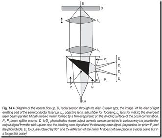
The disc is optically scanned in the player. This is done by AlGaAs semiconductor laser Fig. 14.4 shows the optical part of the pickup. The light from the laser La (wavelength 800 nm) is focused through the lenses Land L onto the reflecting layer of the disc. The diameter of the light spot S, Fig. 14.5, is about 1 µm.
When the light falls on an interval between two pits, the light is almost totally reflected and reaches the fourphotodiodes D1 to D4 via the half-silvered mirror M. When the spot lands on a pit—the depth of a pit is about1/4 of the wavelength in the transparent substrate material—interference causes less light to be reflected and an appreciably smaller amount reaches the photodiodes. When the output signals from the four photodiodes are added together the result is a fairly rough approximation to the rectangular pulse pattern present on the disc in the form of pits and intervals.
The optical pick-up shown in Fig. 14.4 is very small (about 45 × 12 mm) and is mounted in a pivoting arm that enables the pick-up to describe a radial arc across the disc, so that it can scan the complete spiral track. Around the pivotal point of arm is mounted a linear motor that consists of a combination of a coil and a permanent magnet. When the coil is energised the pick-up can be directed to any required part of the track, the locational information being provided by the C & D bits added to each frame on the disc. The pick-up is thus able to find independently any particular passage of music indicated by the listener. When it has been found the pick-up must then follow the track accurately to within ±0.1 µm without being affected by the next or previous track. Since the track on the disc may have some slight eccentricity, and since also the suspension of the turntable is not perfect, the track may have a maximum side-to-side swing of 300 µm. A tracking servo system is therefore necessary to ensure that the deviation between pick-up and track is smaller than the permitted value of + 0.1 µm and in addition, to absorb the consequences of small vibrations of the player.The tracking-error signal is delivered by the four photodiodes D1 to D4 . When the spot S, seen in theradial direction, is situated in the centre of the track, a symmetrical beam is reflected. If the spot lies slightly to one side of the track, however, interference effects cause asymmetry in the reflected beam. This asymmetry is detected by the prism P2 , which splits the beam into two components. Beyond the prism, one componenthas a higher mean intensity than the other. The signal obtained by coupling the photodiodes as (D1 + D2 ) – (D3 + D4 ) can therefore be used as a tracking error signal.
As a result of the aging or soiling of the optical system, the reflected beam may acquire a slowly increasing, more or less constant asymmetry. Owing to a dc component in the tracking error signal, the spot will be slightly off-centre of the track. To compensate for this effect a second tracking error signal is generated. The coil that controls the pick-up arm is therefore supplied with an alternating voltage at 600 Hz, with an amplitude that corresponds to a radial displacement of the spot by +0.05µm. The output sum signal from the four photodiodes which is at a maximum when the spot is at the centre of the track is thus modulated by an alternating voltage of 600 Hz. The amplitude of this 600 Hz signal increases as the spot moves off-centre. In addition the sign of the 600 Hz error signal changes if the spot moves to the other side of the track. This second tracking-error signal is therefore used to correct the error signal mentioned earlier with a direct voltage. The output sum signal from the photodiodes, which is processed in the player to become the audio signal, is thus returned to its maximum value.The depth of focus of the optical pick-up at the position S (see Fig. 14.4) is about 4 µm. The axial deviation of the disc, owing to various mechanical effects, can be maximum of 1 mm. It is evident that a servo system is also necessary to give correct focusing of the pick-up on the reflecting layer. The objective lens L can therefore be displaced in the direction of its optical axis by a combination of a coil and a permanent magnet, in the same way as in a loudspeaker. The focusing-error signal is also provided by the row ofphotodiodes D1 to D4 . If the spot is sharply focused on the disc, two sharp images are precisely locatedbetween D1 and D2 and between D3 and D4 . If the spot is not sharply focused on the disc, the two images onthe photodiodes are not sharp either and have also moved closer together or further apart. The signal obtained by connecting the hotodiodes as (D1 + D4 ) – (D2 + D3 ) can therefore be used for controlling the focusing servo system. The deviation in focusing then remains limited to + 1µm.
RECONSTITUTION OF THE AUDIO SIGNAL
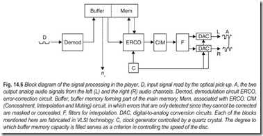
The signal read from the disc by the optical pick-up has to be reconstituted to form the analog audio signal. Fig. 14.6 shows the block diagram of the signal processing in the player.
In Demod the demodulation follows the same rules that were applied to the EFM modulation, but now in the opposite sense. The information is then temporarily stored in a buffer memory and then reaches the Error-Detection and Correction Circuit (ERCO). The parity bits can be used here to correct errors, or just to detect errors if correction is found to be impossible. These errors may originate from a defect in the manufacturing process, damage during use, or finger marks or dust on the disc. Since the information with the CIRC code is interleaved in time, errors that occur at the input of ERCO in one frame are spread over a large number of frames during decoding in ERCO. This increases the probability that the maximum number of correctable errors per frame will not be exceeded. A flaw, such as a scratch, can often produce a train of errors called an error burst. The error-correction code used in ERCO can correct a burst of about 4000 data bits, largely because the errors are spread out in this way.
If more errors than the permitted maximum occur, they can only be detected. In the Concealment, Interpolation and Muting (CIM) block, the errors detected are then masked. If the value of a sample indicates an error, a new value is found by linear interpolation between the preceding value and the next one. If two or more successive sample values indicate an error, they are muted (made equal to zero). At the same time a gradual transition is created to the values preceding and succeeding it by causing a number of values before the error and after it to decrease to zero in a particular pattern.
In the digital-to-analog converter (DAC) the 16 bit samples first pass through interpolation filters F and are then translated and recombined to re-create the original analog signal A from the two audio channels L and R. Since samples must be recombined at exactly the same rate as they are taken from the analog audio signal, the DACs and also CIM and ERCO are synchronised by a clock generator, C, controlled by a quartz crystal.Figure 14.6 also illustrates the control of the disc speed nD . The bit stream leaves the buffer memory at a rate synchronised by the clock generator. The bit stream enters the buffer memory, however, at a rate thatdepends on the speed of revolution of the disc. The extent to which nD and the sampling rate are matched determines the filling degree of the buffer memory. The control is so arranged as to ensure that the buffer memory is at all times filled to 50% of its capacity. The analog signal from the player is thus completely free from wow and flutter, yet with only moderate requirements for the speed control of the disc.
A comparison of the grooves in a conventional LP record and the pits of a compact disc is given in Fig. 14.7.
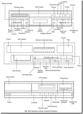
The operating controls typical compact disc (CD) players are illustrated in Fig. 14.8.
EXERCISES
Descriptive Questions
1. What is the difference between an LP record and a compact disc?
2. Explain the following:
(a) channel bits (b) audio bits
(c) parity bits (d) data bits
(e) merging bits
3. What is the function of the tracking-error signal?
4. What is the function of the focusing-error signal?
5. Explain the various steps involved in reconstitution of the audio signal.
6. Briefly explain the operating controls of a CD player.
Multiple Choice Questions
1. On the compact disc, the information is present in the track in
(a) analog form (b) digital form
2. The density of information on a compact disc is
(a) very small (b) very high
3. The diameter of the scanning light spot is
(a) 10 µm (b) 1 µm
(c) 0.1 µm
4. For converting the analog signal from the microphone into a digital signal
(a) A.M. is used (b) FM is used
(c) PCM is used
5. The track is optically scanned from
(a) above the disc (b) below the disc
6. Locational information is provided by
(a) audio bits (b) channel bits
(c) parity bits (d) C & D bits
Fill in the Blanks
1. Each sample is converted into a ……………………………….. .
2. The frequency of sampling should be at least ……………………………….. as high as the highest frequency to be accommodated in the analog signal.
3. One of the functions of C & D bits is providing the……………………………….. for the listener.
4. The optical pick-up is mounted in a…………………………………
5. The information is temporarily stored in a ……………………………….. .
6.The extent to which nD and the sampling rate are matched determines the……………………………….. of the buffer memory.
7. The information with the CIRC code is ………………………………..in time.
8. ……………………………….. memory forms part of the main memory.
9. The analog signal is sampled at a rate of……………………………….. .
10. Parity bits are added in accordance with a coding system called……………………………….. .
11. The pick-up must follow the track accurately to within……………………………….. .
12. A flaw, such as a scratch, can often provide a train of errors called ……………………………….. .
ANSWERS
Multiple Choice Questions
1. (b) 2. (b) 3. (b) 4. (c) 5. (b) 6. (d)
Fill in the Blanks |
||
|
1. binary number 4. pivoting arm 7. interleaved |
2. twice 5. buffer memory 8. Buffer |
3. information 6. filling degree 9. 44.1 kHz |
|
10. CIRC |
11. 0.1 µm |
12. error burst |
