CONTROL CIRCUITS
A modern high fidelity system may have many sources of program material: phono pick-up, A.M or F.M tuners, television, tape, microphone and others. Control centres are available with any degree of complexity one might desire to conveniently provide for the many kinds of inputs, to switch from one to other, apply power to several program sources, control or alter the signal, mix programs, and in general do the many operations used in advanced high fidelity techniques.
INPUT SWITCHING ARRANGEMENTS
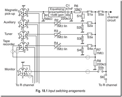
The compatibility of hi-fi units have always difficulties in operation which arises due to incorrect impedance matching and unsatisfactory signal input level. The problem of input and output impedance is much less than hitherto, thanks to standardisation between equipment manufacturers, but the problem of signal level still remains. Fig 18.1 offers a solution to this problem. ResistorsR2, R3 and R4 act as variable input attenuators in conjunction with resistors R7 and R8. Where excessive signal levels are present, adjustment of the preset potentiomenters should be carried out so that the same output power and hence volume, is obtained irrespective of the type of input selected. This will avoid the volume control having a different setting for each input. A suitable level should be first selected with the magnetic pick-up in use, after which the appropriate presets are adjusted for the same volume level. Switch functions are as follows:
S1 — magnetic pick-up S4 — tape playback
S2 —auxiliary input S5 — monitor head
S3 —tuner S6 — mono
Switches S1 to S4 select the input required, whilst shorting to earth the unwanted inputs. Output signal for recording pusposes is taken from the junction of R7 and R8 to the tape recorder socket. Switch S5 connects the amplifier circuit which follows to a monitor tape head, so that the recorded program can be instantly compared with the “original”. This facility applies only to tape recorders with separate record and playback heads, or where an extra monitor head is fitted. Switch S6 combines the L and R-channels for mono.
STEREO BALANCE CONTROL
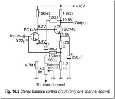
The balance control, Fig. 18.2 makes it possible in streophonic systems to vary the voltage gain in both channels by 6 dB in opposite directions. The controlling variable resistor is inserted in the feedback circuit. The average gain is 23.4 dB. The differences in the total distortion for minimum and maximum gain are slight because of the large amount of feedback applied. The frequency response (–3 dB points) is from <20 Hz to >20 kHz, while the input and output impedances are 140 kΩ and 85 Ω respectively.
STEREO BALANCE INDICATOR
Most stereo equipment is fitted with a balance control to achieve aural equality of the two channels. Lack of sensitivity of the ear in detecting small changes in volume levels can make the operation of balancing somewhat tedious if precision is required and a visual indication that balance has been achieved will ease the task considerably.
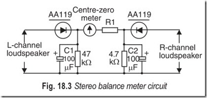
A simple meter circuit which may be used for balancing the outputs in a stereo system is shown in Fig. 18.3. Capacitors C1 and C2 damp the meter movement and resistor R1 is chosen to suit the current rating of the centre—zero moving coil meter and the amplifier output. The value of R1 would be typically 10 kΩ for a meter having a 1 mA movement.
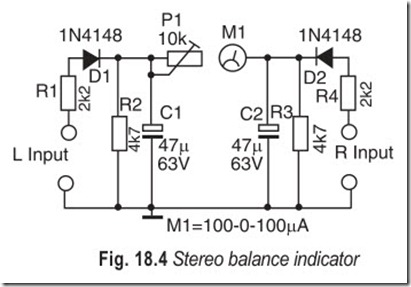
Mechanical deficiencies that affect the sound reproduction in a stereo amplifier are perhaps the last thing you think about when problems are encountered. And yet, they play a larger role than is generally known. Most of such deficienies can be tracked back to the stereo volume control in which the two resistance tracks are often out of step.
The consequent difference in volume between the two channels can normally be evened up by the balance control. If you wish to determine the exact difference, simply connect the stereo balance indicator, illustrated in Fig. 18.4, to the left-hand and right-hand loudspeaker output terminals of the amplifier and feed equal signals—preferably sinusoidal— to the two input channels of the amplifier. If then the signals at the two loudspeaker terminals are exactly of the same level, the centre—zero meter in the balance indicator will not deflect. If, however, the level of the signal in the left-hand channel is higher than that of the signal in the right-hand channel, the meter will deflect towards the left (or towards the right in the opposite case). The balance control can in that case be adjusted till the meter reads zero again: the effect of the volume control tracks being out-of-step has then been eliminated. Preset P1 in the balance indicator should be adjusted for full-scale deflection of the meter when only one channel is operating.
ACTIVE TONE CONTROL
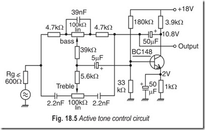
Figure 18.5 illustrates an active tone control circuit which employs a frequency-dependent feedback network between the collector and base of the transistor. For input voltages less than 250 mV the total distortion remains below 0.1%, rising to 0.85% for an output voltage of 2 V at 12,500 Hz. The input and output impedances at 1 kHz are 40 kΩ and 180 Ω respectively.
The range of control extends from –22 to +19 dB at 30 Hz, and from –19 to +19.5 dB at 20 kHz. The flat frequency response is obtained when the variable resistors are in the physically central position. The voltage gain is then 0.91.
SOUND SOURCE WIDTH (DIMENSION) CONTROL
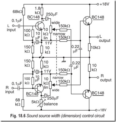
The apparent width of the sound stage can be varied in stereo systems by deliberately introducing cross-talk between the channels, part of the signal voltage of one channel being added to the second channel. The circuit shown in Fig. 18.6 provides continuous control between in-phase cross-talk of 100% corresponding to mono operation and anti-phase cross-talk of 24%. Greater anti-phase cross-talk is not required since the sound impression will fall apart for greater values.
The voltage gain of the circuit is 0.5. Input and output impedances are 750 kΩ and 47 Ω respectively, and the frequency response (–3 dB points) is from 20 Hz to 20000 Hz.
LOW-PASS/HIGH-PASS FILTER
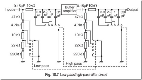
The circuit of a low-pass/high-pass filter is shown in Fig 18.7. It consists of two RC networks connected in series with a buffer amplifier.
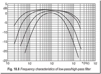
The adjustable frequency characteristics are shown in Fig. 18.8. The following frequency limits can be selected.
Lower frequency 40, 80, 160 and 270 Hz; upper frequency 11, 9, 4.5, 3.2 kHz.
SCRATCH AND RUMBLE FILTER
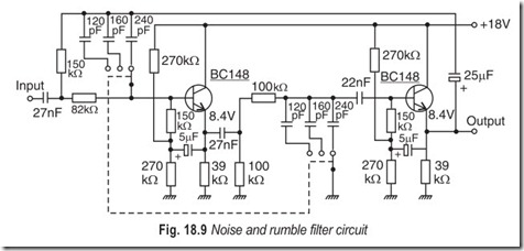
The circuit of a noise and rumble filter is shown in Fig. 18.9. Bass and treble cut are produced by an RC network connected between two emitter-followers, and a feedback loop from the output to the input through a second RC network. In this way, a high slope of about 13 dB per octave is achieved.
The frequency limit of the rumble filter is fixed at 45 Hz, and the noise filter can be switched to limits of 16, 12 and 7 kHz. The voltage gain is 0.95, and the total distortion at 1 kHz and an output voltage of 2 V is 0.35%, falling to less than 0.1% at 1 V. The input and output impedances are 1.7 MΩ and 450 Ω respectively.
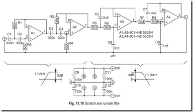
Basically, the purpose of the rumble and scratch filter is to attenuate very low and very high audio frequencies as signals in these frequency ranges generally do more harm than good for the total audio signal. Another way of considering this circuit is to see it as a very wide band-pass filter for the band containing the most important part of the audio spectrum.
The layout of the circuit shown in Fig. 18.10 is quite simple as it consists of two filters in series, a low- reject followed by a high reject. Each filter consists of a pair of cascaded second-order filter stages to achieve a very steep characteristic of 24 dB/octave. The cut-off frequencies are 11.8 Hz and 10.7 kHz with the component values given, The suitability of these points depends on the application and it is not at all difficult to change them. The 11.8 Hz cut off frequency can be increased by reducing the value of capacitors C1………..C4, or it can be lowered by increasing the capacitance. These capacitors must all have the same value. The 10.7 kHz cut-off frequency can also be modified by changing the value of resistors R5…………R8. Like the capacitors, these four resistors must all have the same value but this value can be reduced to increase the cut-off frequency or raised to lower the cut-off frequency.
The op-amps used are low-noise type and there are two in each IC package. Two ICs are, therefore, required for each channel. Current consumption per channel is about 20 mA.
BASS AND TREBLE CONTROLS
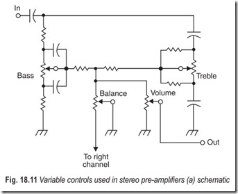
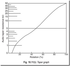
Figure 18.11(a) is a schematic representation that shows all the stereo preamplifier controls: bass, treble, volume and balance. The balance control is a 100k linear-taper potentiometer; all other potentiometers must have an audio taper. The audio taper applies a rather logarithmic characteristic to the control as shown in the taper graph in Fig. 18.11(b).
When the control is set at mid-position, 10 per cent of the total resistance of the potentiometer is on one side of the wiper arm and 90 per cent is on the other. When the control for the bass is set at mid-position, the response is flat down to about 50 Hz. When the treble control is set to the centre position, the frequency response of the high end is flat down to about 50 Hz.
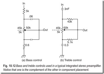
Bass Boost and Cut: Examining the bass control circuit as a separate item, Fig. 18.12(a), you can see the control concept of the passive circuit. In the centre position, a 5 kΩ resistance appears from the wiper arm toward the ground side of the potentiometer and a 45 kΩ resistance appears on the other side (for a total value of 50 kΩ across the potentiometer). At 50 Hz, the reactance of the capacitor on the “hot” side is made equal to the 45 kΩ portion of the controls and the reactance of the “cold side” capacitor is equal to the 5 kΩ portion. As the frequency increases, the hot side capacitor couples more signal to the output while the cold side capacitor shunts more signal to ground through its series resistor. This results in a flat response over the amplifier’s frequency range with an insertion loss of 20 dB.
When the wiper arm of the bass control is in the boost position, the cold side capacitor—with a reactance of 10 per cent of the control at 50 Hz effectively shunts the control output circuit. This makes the series resistor on the hot side of the line and the cold side capacitor the components that are dominant in shaping the frequency response characteristic. The full bass-boost position will supply an output voltage at 50 Hz that is 20 dB greater than the “flat” position. Hundred per cent boost represents zero attenuation in the tone control of the lower frequencies. The output volume will decrease at about 6 dB per octave until the point where the reactance of the cold side capacitor is not a factor, at which point the amplitude will be determined by the ratio of the resistors on either side of the bass control. In the minimum position (full bass cut), the output level at 50 Hz is determined by the ratio of the capacitive reactance of the hot side capacitor to the series resistor on the ground side of the potentiometer, which should be about 40 dB below the level indicated by the input voltage. As the frequency increases, the reactance of the hot side capacitor decreases until it is equal to the resistance of the ground-side series resistor, which again makes the output level a function of the ratio of the hot-side series resistor to the cold-side series resistor.
In normal operation, the frequency at which roll off begins (a deviation of 3 dB from the flat response curve) will vary according to the setting of the control, but the actual slope of the curve will remain fairly constant. In examining the frequency response of the bass control circuit, the 0 dB point is referred to as the boost-or-cut axis, even though this position is actually 20 dB below the input signal level.
Treble Boost and Cut: Fig 18.12 (b) shows the treble control circuit separate from the preamplifier so that its operation can be better understood. Except for the potentiometer, the circuit is the electronic inverse of the bass control; that is, where the bass control uses resistances, the treble control uses capacitances and the treble circuit employs resistances where the bass circuit uses capacitances. At frequencies below 2 kHz, the reactance of the two feeder capacitors form a 10:1 divider, resulting in a 20 dB insertion loss. Above 2 kHz the two reactances are small relative to the parallel resistive divider combination of the control, which provides 10:1 voltage division to maintain the 20dB insertion loss over the high frequency region. In all, the result is an insertion loss of 20 dB over the entire range from 20 Hz to 20 kHz.
Fig. 18.12 Bass and treble controls used in a typical integrated stereo preamplifier. Notice that one is the complement of the other in component placement.
At full boost, the hot-side capacitor has a reactance that is roughly equal to the total resistance of the potentiometer at a frequency slightly greater than 2 kHz, so half the input voltage appears at the control output, With voltage halving is cutting by 6 dB, which is the equivalent of a 14 dB treble boost at 2 kHz where it should be 3 dB (The 6 dB is subtracted from the 20 dB insertion loss, giving 14 dB of treble boost). By placing a resistor from the wiper to the ground side of the control, with a value equal to the centre- position resistance (5 kΩ), the ratio of the capacitive reactance to this resistor causes a sure boost starting at 2 kHz.
Considering the effects of all the controls (bass, volume and balance), the boost works out to be 7 dB rather than 14 dB (without the ground side resistor in the circuit). The resistor on the hot-side of the potentiometer, though corrects for this and gives a smooth boost active over the entire range of the control. Without this additional resistor, all the boost action would occur at the end of the potentiometer’s range.
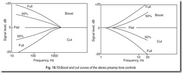
In the cut position (control turned counter clockwise from centre), the hot-side resistor in parallel with the hot-side capacitor and the control itself are the frequency-response determining conponents. From 2 kHz on up, the reactance of the cold-side capacitor decreases until, at about 29 kHz, there is a 20 dB amplitude reduction. Intermediate settings of the control allow a fairly constant roll off slope with a changing roll off frequency. Fig. 18.13 shows the normalised bass and treble boost and cut curves from full cut to full boost.
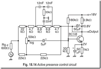
Presence Control: The active presence control circuit shown in Fig. 18.14 uses frequency selective negative feedback with amplitude control to achieve up to 13 dB boost at 2000 Hz. The feedback network is a bridged-T filter.
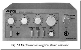
The controls on a typical stereo amplifier (Supra Japan) are illustrated in Fig. 18.15.
TSA-901 Stereo Amplifier
Effective power output
30 + 30 watts at 8 ohms Max 50 W + 50 W (Both channel driven)
Harmonic Distortion
Less than 0.15% at rated output
Frequency Response 20–
40,000 Hz + 2 dB
Controls
Volume, Balance, Bass and Treble
Switches
Selector (Phono, Tuner and Aux),
Loudness, Mode, Tape Monitor and Power
Semiconductors
19 Silicon Transistors, 9 Silicon Diodes
Dimensions
200(W) × 85(H) × 250 (D)mm
EXERCISES
Descriptive Questions
1. Describe a typical input switching arrangement.
2. What is the need for a stereo balance control?
3. How will you fit a stereo balance indicator?
4. Briefly explain an active tone control. How does it differ from a passive tone control?
5. Explain (a) bass boost and cut and (b) treble boost and cut.
6. What are the controls normally found on a stereo amplifier? Briefly explain the significance of these controls.
Fill in the Blanks
1. Many difficulties in operation of hi-fi systems have arisen due to ………………………………….. impedance matching and ………………………………….. input signal level.
2. The balance control makes it possible in stereophonic systems to vary the………………………………….. gain of both channels by………………………………….. in ………………………………….. directions.
3. The apparent width of the sound stage can be varied in stereo systems by………………………………….. introducing………………………………….. between the channels.
4. The balance control is a ………………………………….. taper potentiometer, all other controls must have an audio…………………………………..
ANSWERS
Fill in the Blanks
1. incorrect, unsatisfactory 2. voltage, 6 dB, opposite 3. deliberately, cross-talk
4. linear, taper
