COMMERCIAL SOUND
Sound is commercial to the extent that a segment of the public has a preference for the same audio qualities, consciously or subconsciously.
But preferences change gradually, and usually in favour of the more realistic effect, because that, ultimately is the easiest to listen to. Artificial effects, ultimately become tiring. What may have started as a wonderful sound does not continue to satisfy because it cannot be identified as something real.
This has been one of the problems that electronically-generated forms of music have had in gaining acceptance. And studios are becoming more and more involved in these devices. We are living in days when purely electronic sounds, that are not intended to simulate some older sound form, are beginning to gain acceptance in their own right.
ELECTRIC GUITAR
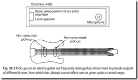
The guitar, Fig. 26.1, was the first instrument to make popular use of electronics. Electric guitars use a suitable pickup to transduce the motion of the guitar strings to electrical signals. These signals may be amplified and fed into one or more loudspeakers, and usually provision is made to modify the character of sound in several ways. The tone may be modified so that a guitar of a given form and size, with a fixed tone capability without electronics, can be made to sound like many instruments in the guitar family through the use of electronics. In addition, either vibrato or tremolo can be added to tones electronically, and a variety of novelty effects, such as “fuzz tone” can be produced.
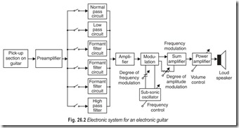
A typical United States patent describes a system for electric guitars and the like as illustrated in Fig. 26.2 and as modified in Fig 26.3. The pick-up section on the guitar may consist of one or more electromagnetic or piezoelectric transducers per string. The output of the pick-up section is in electrical form representing the tones, including all partials, generated by the vibrating strings of the instrument. The design of the pick-ups and their locations with respect to the strings influence the relative amplitudes of the partials of the tones, but the positions selected for the system of Fig. 26.2 provide a full complement of partials.
The electrical signals produced by the pick-up section in Fig. 26.2 are amplified by an isolating amplifier and passed to a series of circuits which may be selected individually or in combination by means of switches. This series of circuits may include a circuit which passes all partials without colouration, a circuit which passes low-frequencies with less attenuation, one or more circuits that accentuate, one or more bands of frequencies (called formant filters), and a circuit that favors the passage of high-frequency signals and attenuates low-frequencies. This series of circuits enables the musician to select the sound of the acoustic guitar, rock-and-roll guitar, classic guitar, Hawaiian guitar, bass guitar, solo guitar, and other sounds. After the electrical signals have passed through one or more colouration circuits, they are again amplified and passed to a modulator circuit that makes use of a low-frequency (subsonic) oscillator to add a vibrato or tremolo effect or both at a desired degree and rate. The tone signals are again amplified and passed to one or more loudspeakers, with a suitable volume control provided.
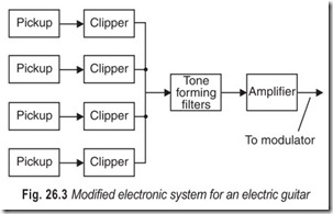
The system illustrated in Fig. 26.3 provides clipper circuits between the pick-ups and the tone-forming filters. The clipper circuits generally serve to augment the strength and number of partials so as to provide greater possibilities for variety in the tone-forming filters. The tone-forming circuits may be the same as those shown in Fig. 26.2, or may be different. The resulting signals may be treated as in Fig. 26.2.
ELECTRIC WIND INSTRUMENTS
The treatment discussed above can also be given to the tones of the other stringed instruments including pianos, and to wind instruments also.
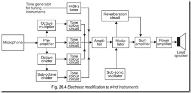
In wind instruments only one pick-up is generally used, a sound-pressure microphone placed in the mouthpiece or in some other part of the instruments. The electrical signals from the pick-up micrphone can be treated in ways similar to those illustrated in Fig. 26.2 or 26.3.
The block diagram in Fig. 26.4 indicates a simplified composite of functions offered on different commercial products to be used to either amplify or modify, or both amplify and modify the tones of individual wind instruments.
In addition to tone modifications in timbre, tremolo or vibrato embellishment and virtually unlimited sound power it is possible for one instrument to sound as if it were as many as four octavely-related instruments playing simultaneously. This is done by circuits that divide or multiply the fundamental frequency of the tone produced by the instrument played by the musician. Also, artificial reverberation or echo effects can be added to the tone.
The 440 Hz tuner shown in Fig. 26.4 is an oscillator that can be used to produce standard note A for tuning the instrument being played.
Electronic systems to amplify and modify tone of individual musical instruments are being used in marching bands, concerts, motion picture sound tracks, recording, and many other ways.
RECORDING
In electronic music synthesizer systems, a single series of tones is generated at a time. As a result, all of the characteristics of a tone can be applied to each tone in a series of tones. This is, of course, impossible in the case of conventional musical instruments or in the case of all-electronic musical instruments because, in general, more than one tone is generated at a time. As a matter of fact, the entire composition is produced in one run. The electronic music synthesizers provide the most powerful system for the generation of musical sound and the resultant production of recorded music yet invented.
When a single series of tones is produced by a manual electronic music synthesizer, by a programmed electronic music synthesizer, or by a computer, the recording is essentially made with a synchronised multi- channel magnetic tape-recorder. In this way, the magnetic tape recorder can be synchronised with any picture or program. Some form of synchronised multi-channel recorder is employed in all types of electronic music synthesis.
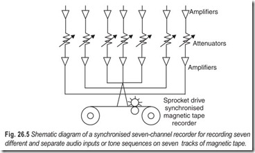
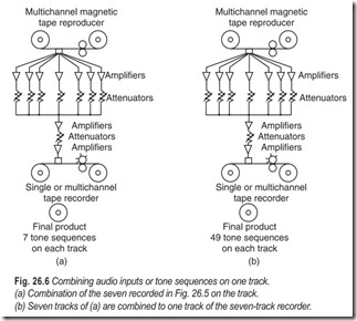
Seven different audio inputs representing seven series of tones are recorded on seven separate tracks, Fig. 26.5. This magnetic tape is reproduced, and the audio signals in the seven channels are mixed and recorded on a signle track of a seven-track recorder, Fig. 26.6 (a). When the seven tracks of this recorder are filled with seven different operations, the recorded tape is reproduced and combined to a single track representing 49 tone sequences, Fig. 26.6 (b). If the recorder in Fig. 26.6 (a) is a seven-channel recorder and all the tracks are filled, the total final result represents 343 tone sequences. These can be combined to a single track again, and so on.
MANUAL SYNTHESIZER
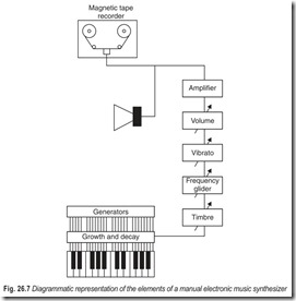
The manually operated electronic music synthesizer, Fig. 26.7, is based upon the generation of the properties of a tone to produce the desired final musical tone. In the synthesizer in Fig. 26.7 only one series of tones is produced at a time. Each series of tones is recorded with a recorder of the type shown in Fig. 26.5. The various different series of tones are combined as depicted in Figs. 26.5 and 26.6 and as described above.
The synthesizer in Fig. 26.7 can produce a tremendous range of tones with all manner of variation in each series of tones; this cannot be done with the electronic organ. For example, the performer changes the volume, timbre, and some of the other characteristics with one hand, while he plays on the keyboard with the other hand. Therefore, great physical dexterity and considerable musical talents are required to produce acceptable music by means of the electronic music synthesizer. The main reason for this is that each series of tones must possess distinct musical qualities in order to produce musical effects beyond the conventional. In addition, there must be a perfect synchronism of the different series of tones which is also carried out subjectively, that is by ear.
PROGRAMMED SYNTHESIZER
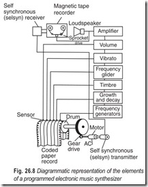
The use of a programmed electronic music synthesizer opens up an entirely new field for the production of recorded music, Fig. 26.8. To synthesize or produce any musical tone whatsoever, the programmed electronic music synthesizer must provide the facilities for producing all the characteristics of a tone.
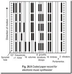
The program for each series of musical tones is recorded on the coded paper record, which controls all the functions of the electronic music synthesizer. The information is recorded and stored in the paper record in the form of black ink lines.
When the paper is run through the machine, the sensors scan the paper record. The paper record, Fig. 26.9, shows that a binary code system is used. With the use of this system, 2 different functions can be obtained from 1 track, 4 from 2 tracks, 8 from 3 tracks and 16 from 4 tracks, and so forth.
The preparation of the record of Fig. 26.9 is simple. The musician simply marks the paper with a wide ink pen to obtain the type of sound he desires. The marking of the paper can be done anywhere. After the record is completed, the musician runs the record through the synthesizer and listens to the series of tones by means of the loudspeaker. If he is not satisfied, he can make changes by adding new lines or by marking out existing lines with a white marker. In general, no changes are required for the frequencies because they are taken directly from the music. The length of the lines is determined from the note. Therefore, except for errors, the frequency markings are straight forward. As mentioned, changes can be made in the other functions. After the record is satisfactory, the paper record is recorded on magnetic tape, Fig. 26.5. This process is carried out for each series of tones until all of the series of tones of the composition have been completed. The method of combining the series of tones has been described earlier and shown in Figs. 26.5 and 26.6.
Entirely new tone complexes and combinations which cannot be achieved with conventional instruments are possible with the programmed synthesizer. With conventional instruments the musician is limited to the use of lips, mouth, fingers, hands, and feet to perform the different functions. In the programmed electronic music synthesizer, there are no such limitations. In addition, in the case of manual operation, there is the problem of synchronising the various series of tones. However, in the programmed electronic music synthesizer, as is evident from the direct drive between the paper record and the magnetic tape recorder, there is no problem of synchronising the series of tones.
DIGITAL COMPUTER
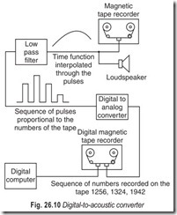
Music may be synthesized by means of a digital computer. The key process involves a digital-to-acoustic converter. A schematic block diagram of the conversion process is shown in Fig. 26.10. A magnetic tape is prepared by the computer, on which are recorded successive digitized samples of the acoustic output. The numbers are then converted to pulses, the amplitudes of which are proportional to the numbers. The pulses are smoothed by a low-pass filter to obtain the input for an audio loudspeaker. If the sampling rate is 20,000 per second, the top frequency from the loudspeaker will be 10,000 Hz. Each sample is produced from a four-decimal number. The signal to noise ratio will be of the order of 60 dB. Within the limits of frequency range and signal to noise ratio, the converter can produce any sound, whatsoever, provided the appropriate sequence of digital samples can be generated.
The basic form of the generating program is a scheme for producing a sequence of sounds representing individual instruments. The instruments are formed by combining a set of basic building blocks called unit generators. Appropriate combinations of these unit generators can produce sounds of almost any desired complexity.
The first step in the production of a musical selection is to punch a set of cards which specify the instruments of the orchestra. The instruments and the computing program are fed into the computer, which punches a card deck that is the music generating programor orchestra. Next a series of note cards or score must be prepared. These provide the properties of a tone.
As in the case of the programmed synthesizer, the process is simplified if the composer listens to one series of notes at a time, makes suitable modifications, and then groups the combination of tones after each one has been approved. Minor modifications can then be made in the group, if necessary. The series of tones are then recorded as depicted in Figs. 26.5 and 26.6.
The exposition given above has described one process for the electronic synthesis of music employing a digital computer. As the programming for computers is simplified, the general procedure will also be simplified. However, the composer operating the synthesizer, regardless of the method employed for the electronic synthesis of music, is the final judge of the rendition. The analog and digital synthesizers can produce any tone, regardless of whether it has ever been produced before. Therefore, the method which will be selected is the one that provides the composer with the easiest means for translating what he has in mind into the final sound product.
PUBLIC ADDRESS SYSTEMS
A public address (PA) system consists basically of a microphone, amplifier and speaker(s) to facilitate the communication of intelligible speech to groups of people. Coverage of large groups may be the chief purpose of providing communication over outdoor areas or of providing sound reinforcement indoors with sufficient fidelity so that the sound system is unobtrusive.
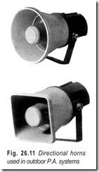
Acoustic problems differ considerably for outdoor and for indoor installations. Directional horns, Fig 26.11, are often employed in outdoor systems to concentrate sound energy efficiently over the areas served. Intelligibility is the usual performance criterion and the system frequency response is typically limited to a range of 300 Hz to 5,000 Hz. Intelligibility may also be the performance criterion for an indoor system such as an airport waiting room. On the other hand, high-fidelity reproduction is required for a sound- reinforcement system, for instance a concert hall.
Outdoor installations utilising directional horns require approximately 2 watts of audio power per 1000 square feet and operate at efficiencies up to 50 per cent. Sound reflection from stadium walls, grandstands, fences or buildings may increase this sound level, but often at the expense of intelligibility. Therefore, the acoustics of the served area are often a dominant consideration in system design.
Reliability is often a basic requirement, necessitating more or less duplication of facilities, arranged so that service will not be interrupted in the event of some equipment failure. In other words, if one of the high- power amplifiers fails, it is desirable that service continues, even at a reduced sound level. Similarly, if a speaker or line should fail, it is desirable that the remaining speakers and lines continue to operate normally.
Indoor sound reinforcement systems generally employ wide range speakers. A minimum audio power of 50 watts is required for seating capacities upto 500, and an additional 50 watts for capacities upto 1000, and so on. It is good practice for the control operator to be stationed in a room communicating with the served area, so that audio levels can be controlled in accordance with realistic requirements, and maintained at a level sufficient to override prevailing audience noise.
Installations operating at comparatively high audio power level, either outdoors or indoors, have been standardised in accordance with the 70.7 volt speaker matching system established by the Electronic Industries Association (EIA). The system reduces losses in the wiring, and increases operating efficiency.
PLANNING A PUBLIC ADDRESS SYSTEM
As a general rule, planning of a PA system starts with :
(i) calculation of the area to be served,
(ii)estimation of the required audio power,
(iii) choice of the types of speakers to be utilised, and
(iv) estimating the approximate number of speakers.
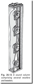
As an illustration, most office areas can be served satisfactorily with 8 inch cone speakers rated at 1/2 watt each. Ceiling speakers are installed about 25 feet apart. Warehouses or meeting halls often require 5 watt speakers mounted from 25 to 50 feet apart. When noise is troublesome, 5 watt indoor horn speakers may be installed at necessary locations to maintain a satisfactory audio to noise ratio. Speakers serving spectator groups in outdoor installations should be placed near the audience. For distance coverage upto 1/2 mile, clustered projectors are employed. School auditoriums are best served bysound columns, comprised of several speakers mounted in the same vertical or horizontal housing, as shown in Fig. 26.12.
After the required audio power has been determined by adding the power ratings of speakers in the system, a suitable amplifier is chosen. It is a good practice to operate an amplifier below its maximum—rated output level. For example, if 6 horn-type speakers rated at 6 watts each and 5 cone-type speakers at 3 watts each are used, the total audio power requirement is 51 watts. In turn, an 80 watt amplifier would be a conservative choice, permitting the addition of a few special speakers in the event they may be needed.
Most PA amplifiers have provisions for one or more microphones and one or more other sound sources such as f.m/a.m radio, tuner outputs, tv sound output, tape-recorder and record-player outputs. Level (fader) controls may be provided to adjust the volume from each of several sources simultaneously.
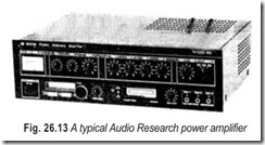
High-input impedances are generally provided and matching transformers can be employed to accommodate low-impedance sound sources. Fig. 26.13 illustrates a typical Audio Research amplifier.
Most PA amplifiers have speaker outputs for a constant voltage system ( either 25 or 70.7 volts) plus 4, 8 and 16 W outputs to match voice coils directly. A 25 volt system is easy to instal because conduit is not required. On the other hand, a 70.7 volt system provides comparatively high operation efficiency.
After the amplifier has been selected, suitable microphones should be considered. The choice of microphones is chiefly determined by intended use. In other words, no one microphone will perform equally well under all conditions. The basic considerations are :
(a) the pick-up element that is utilised,
(b) the pick-up pattern that is optimum for the location, and
(c) the conditions under which the microphones have to operate.
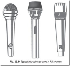
Ceramic microphones are comparatively inexpensive, have relatively high output and wide frequency response and resist climatic changes. Dynamic microphones resist shock and bad weather conditions, have superior frequency response and fidelity, and are well suited for orchestral or vocal reproduction. Carbon microphones are inexpensive and rugged, have high sensitivity and also have the disadvantages of inferior frequency response and comparatively high distortion. Typical microphones used in PA systems are shown in Fig. 26.14.
A detailed description of different types of microphones is given in Chapter 2. Ceramic and dynamic microphones are generally recommended for the reproduction of speech and music. High-quality dynamic microphones, sometimes calledbroadcast-quality microphones have high fidelity response and are commonly used with PA systems for auditoriums, stage groups, theatres, and concert halls. Carbon microphones are utility-type tranducers and are used only in systems where economy is desired and high-quality reproduction is not necessary.
Microphones generally have substantially better characteristics than speakers. Microphones are also affected less by poor acoustics than are speakers. In many PA systems a wide choice of microphones is permissible whereas speaker type, placement and energisation may be critical and demanding.
SPEAKER MATCHING SYSTEMS
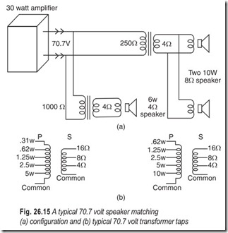
Speaker matching systems permit higher operating efficiency in audio power systems. The 70.7 volt system is preferred for high-power PA networks. Fig. 26.15 illustrates such a network for three speakers. A matching transformer is installed to match a speaker or a group of speakers to the 70.7 volt line. This is called a constant-voltage system because the line voltage is comparatively unaffected by switching speakers on or off. Network calculations are as follows :
1. Determine the power rating of each speaker.
2. Add the power rating to find the total power demand and use a 70.7 volt amplifier with a rated power output at least equal to this demand.
3. Select a 70.7 volt matching transformer for each speaker, or for each group of speakers, Fig. 26.15, with appropriate primary wattage ratings.
4. Connect the primary terminals of each transformer across the 70.7 volt line from the amplifier output. Note that a primary mismatch up to 25 per cent is tolerable.
5. Connect the secondary terminals of each transformer to its speaker, or group of speakers, observing the matching ohms taps.
6. In case the matching transformers are rated in impedance values, the primary wattage of a transformer may be calculated as follows.
where Zp is the rated primary impedance and P is the wattage rating of the speaker.
Problem 26.1 Calculate the power rating of the amplifier in Fig. 26.15
Solution The power demand of the speakers = 26 watts.
The amplifier rating = 30 Watt (approx)
Problem 26.2 In the above example, calculate the impedance of the primary windings.
Solution The primary impedance for
A 1000 Ω impedance could be utilised.
the 20 watt speaker combination = 250 Ω (approx.)
PA SYSTEM CHARACTERISTICS
In speech reinforcement systems the listener hears sound from two sources. Part of the sound comes from the person making the speech; yet another part of the sounds comes from the PA system. The total sound that arrives is greater than that from either source alone, but the two portions do not arrive simultaneously. From a practical viewpoint, the maximum tolerable time delay between the two arriving wavefronts is approximately 25 milliseconds. A longer time delay is likely to result in a confusing separation of the two sound sources; the listener’s attention jumps from one source to the other and becomes distracted. Since the human ear has a natural tolerance for echo effects, an echo tends to be disregarded under ordinary conditions. However, if the echo arrives too long after the original wavefront, it is no longer disregarded and the listener becomes uncomfortably aware of the split-sound sources. Therefore, it is good practice to plan a PA system so that no listener will be exposed to two arriving wavefronts that have a time delay greater than approximately 25 milliseconds. That is called the Haas effect.
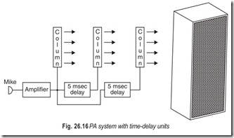
A cluster of speakers, or a speaker column, will provide considerable sound coverage. However, in large buildings that have appreciable reverberation, a large speaker column may need to be supplemented by smaller columns placed farther back from the sound source. A supplementary speaker column, Fig. 26.16 can be installed with a time-delay circuit so that the sound from the first column arrives 5 millisecond before the sound from the second column is radiated. The intensity of the delayed sound should not be more than 10 dB greater than that of the first-arriving sound, otherwise separation is likely to become evident. Time delay units for PA systems generally employ a tape deck with spaced playback recording and playback heads, or a magnetic disc.
PUBLIC ADDRESS AMPLIFIERS
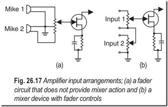
A PA amplifier may be designed as a unit, or it may consist of separate amplifiers. When more than one audio input source is utilised (two-microphones, for example) operating controls are provided to change from one source to the other, or to mix the outputs of the sources, The mixer and fader section is designed to provide flexibility of operation without sudden increases or decreases in volume. A fader serves to gradually reduce the volume of one source while gradually increasing the volume of another source. A mixer may or may not provide fader action.
A microphone amplifier provides preliminary step-up of the microphone output signal. The power amplifier is driven by an intermediate amplifier which is basically similar to a microphone amplifier except that it may employ high power transistors. If a power amplifier has sufficient gain it may be driven directly by the microphone amplifier.
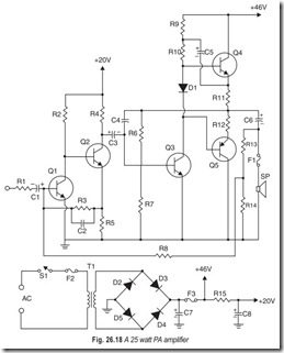
The complementary symmetry public address audio amplifier, Fig. 26.18, is rated at 25 watts audio power. For stereo operation, the amplifier circuit is doubled, using the single power supply for both channels. Since this is a basic power amplifier, a suitable preamplifier is required. The balanced bridge power supply helps eliminate ripple, resulting in noise-free reproduction. A dual voltage output is obtained across dropping resistor R15.
This amplifier can be used in a number of applications, provided there is suitable drive from a preamplifier. Typical applications include high fidelity. It can also be used in an electronic organ, as a playback amplifier for a tape deck, and the 25 watts of audio power is sufficient for use as a musical instrument amplifier.
MEGAPHONES
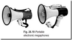
Portable electronic megaphones, Fig. 26.19 are used by construction workers, law-enforcement officials, boat navigators and so on. The unit comprises a reentrant horn speaker with a microphone mounted on the back.
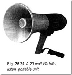
A 5-transistor class-B amplifier is typically employed to step-up the microphone signal. The unit is powered with a 9 volt battery and has a maximum output of 8 watts with a sound range of 600 yards. A volume control is provided and a built in siren signal source is available in the unit shown in Fig. 26.19. Yet another design is shown in Fig. 26.20. This is a 20 watt unit and provides more than twice as much as the portable unit. A switch is provided to change the circuit configuration into a sensitive directional listening arrangement. An input jack is available for feeding in a signal from a record player, tape player, or radio tuner.
INTERCOMMUNICATION EQUIPMENT
Intercommunication units are classified into master and remote types. A master station can call any one of the remote stations. On the other hand, a remote station can call the master station only. An intercommunication wiring system may employ master stations throughout. In this case, any station can call any other station. This type of intercom set has remote units with beep buttons that permit a caller to signal the master station even when the system is turned off.
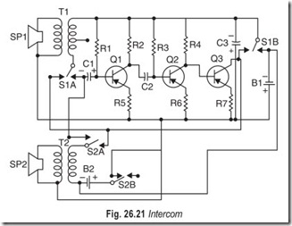
The intercom circuit shown in Fig. 26.21 is a 3-transistor amplifier with a slightly sophisticated switching circuit. Each speaker serves the dual function of microphone and loudspeaker, with the switches determining what that function is. When S1 is in talk position. T1 feeds the base of Q1 through C1 . SP1 does indeed serveas a microphone. At the same time, S1B is connected so that the output signal from Q3 emitter circuit isconnected to transformer T2feeding the signal to SP2 which then functions as a loudspeaker. With the circuitoperating in this fashion, whatever is spoken into SP1 will be heard in SP2 . By reversing switch S1 , you reverse the process. S2 also provides a calling signal by feeding the amplifier output signal back to the input, causing it to oscillate and howl.
The remote unit consists only of SP2 , S2 and B2 . Additional remote units may be added, connecting them the same as the first one, using 4-conductor cable.
BACKGROUND MUSIC AND PAGING SYSTEMS
Background music may at first seem to be merely an amenity, but it has proven economic value. Music- while-you-work was introduced during World War II because it was found to boost production at a time when there was a manpower shortage. In stores, background music puts buyers in a happier mood and the sales go up. In airports and other public buildings, it may have no direct economic advantage, but as background music is now readily available, and a paging system is virtually a necessity, the surroundings can be rendered more pleasant by utilising the system for background music, while it is on stand by.
Background music is chosen to be unobtrusive, not requiring listener concentration for its enjoyment. And the reproduction is not so wide-range as either high fidelity in the house, or musical program broadcast. Reducing the response to lower frequencies enables smaller speakers (physical size) to be used and reducing the upper frequencies lends a pleasant roundness to the reproduction that helps to ensure its unobtrusiveness.
Paging systems fit in quite naturally with background music, using microphones at certain control locations for feeding necessary paging announcements to the system. At an airport, for example, each airline will have a microphone to enable the counter to page customers who may have failed to pick-up their tickets or other material or for whom telephone messages may be waiting.
Complex paging systems are built up of relatively simple units. Microphone inputs feed into immediate microphone amplifiers and power amplifiers feed sections of loudspeakers, and the outputs from groups of microphone amplifiers are fed to the appropriate power amplifiers so that correct groups of areas are covered with each group of announcements. One more thing in such a complex system: the indication whether the system, or any part of it, is free from a particular announcement. This is achieved by a system of lights, keyed by a microphone in use to indicate to all other microphone stations, that might want to use the same group or groups of speakers, that the system is in use.
A more sophisticated system might include an electrical (by means of relays) or electronic (by means of signal-gating circuits) interlock to ensure that accidental pressing of another key will not interfere with announcement in progress.
EXERCISES
Descriptive Questions
1. Explain briefly the working of an electric guitar.
2. How does an electric wind instrument work?
3. Explain the working of a manual synthesizer.
4. How does a manual synthesizer differ from a programmed synthesizer?
5. What is the difference between a public address system and a sound reinforcement system?
6. How will you plan a public address system?
7. What are the different types of microphones used with public address systems?
8. Explain the significance of a speaker matching system.
9. What is the difference between a PA system and a megaphone?
10. Why background music is required?
11. Explain the working of a simple intercom system with the help of a diagram.
12. Write short noes on :
(a) Formant filter (b) Haas effect
(c) Paging
Multiple Choice Questions
1. In electric guitars provision is made to
(a) amplify the character of sound
(b) modify the character of sound
(c) amplify or modify the character of sound
(d) amplify & modify the character of sound
2. Circuits that accentuate one or more bands of frequencies are called
(a) band pass filters (b) formant filters
(c) low pass filters (d) high pass filters
3. In electronic music synthesizer systems
(a) series of tones are generated at a time
(b) a single tone is generated at a time
(c) a single series of tones is generated at a time
4. Music synthesis by means of a digital computer involves a
(a) digital-to-acoustic converter
(b) acoustic-to-digital converter
(c) analog-to-acoustic converter
(d) acoustic-to-analog convertor
5. High fidelity reproduction is required for a
(a) public address system (b) intercom system
(c) sound reinforcement system (d) paging system
6. School auditoriums are best served by
(a) woofers (b) tweeters
(c) sound columns (d) loudspeaker system
7. The maximum tolerable time delay between two arriving wavefronts is
(a) 5 ms (b) 15 ms
(c) 25 ms (d) 35 ms
8. A sophisticated paging system may include
(a) amplifiers (b) relays
(c) oscillators (d) signal-gating circuits
9. A master station (intercom) can call
(a) only one remote station (b) any one of the remote stations
(c) only two remote stations (d) any two of the remote stations
Fill in the Blanks
1. In an electric guitar provision is made to ………………………………. the character of sound in many ways.
2. The pick-up section on the guitar may consist of one or more ………………………………. or transducers per string.
3. The clipper circuits generally serve to augment the strength and number of partials so as to provide greater possibilities for ………………………………. in the tone-forming filters.
4. Electronic systems to………………………………. and modify tones of individual musical instruments are being used extensively.
5. A public address system facilitates the………………………………. of intelligible speech to groups of people.
6. In a public address system the frequency response is typically limited to a range of………………………………. .
7. In a public address system………………………………. is often a basic requirement.
8. Indoor sound-reinforcement systems generally employ a………………………………. range of speakers.
9. Speaker matching systems reduce losses in the wiring and increase………………………………. .
10. It is good practice to operate an amplifier………………………………. its maximum rated output level.
11. Most PA amplifiers have outputs for a………………………………. system.
12. The choice of microphones is chiefly determined by………………………………. .
13. Microphones generally have substantially………………………………. characteristics than speakers.
14. In speech reinforcement systems the listener hears sound from………………………………. .
15. The maximum tolerable time delay between two arriving wavefronts is………………………………. .
ANSWERS
Multiple Choice Questions
|
1. (b) |
2. (b) |
3. (c) |
4. (a) |
5. (c) |
6. (c) |
|
7. (c) |
8. (b) & (d) |
9. (b) |
Fill in the Blanks
1. modify 2. electromagnetic or piezoelectric 3. variety
4. amplify 5. communication 6. 300 to 5000 Hz
7. reliability 8. wide 9. efficiency
10. below 11. constant voltage 12. internal use
13. better 14. two sources 15. 25 ms
