ELECTRONIC MUSIC SYNTHESIZERS
The first Moog synthesizers were made available only in 1964. While electronic musical instruments consist of basically simple circuits, or building blocks, the instrument itself is usually a complex, sophisticated device.
Electronic musical instruments differ markedly from conventional or traditional musical instruments. Electronic instruments use electrons to generate the signals that make up the sounds and in appearance an electronic musical instrument resembles a computer more than a ‘musical instrument’. They are often as complex as a computer to operate as well, demanding of the composer and or player an expertise beyond the knowledge of musicology.
Pioneers in the field of “new” music recognise that it has a deep spiritual basis. Electronic music encompasses many disciplines by combining different aspects of science, music, and philosophy- even theatre. People who look down on “music by machines” fail to realise that electronic music was not designed to replace humans; rather, it brings a powerful new tool to the hands of the musician.
TYPICAL GENERATORS
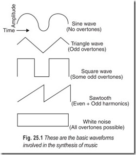
Periodic or cyclic waveforms sine, square, sawtooth, and triangle waves–form the backbone of electronic music generators (see Fig. 25.1). Most instruments (synthesizers) contain as many as several dozen oscillators, each capable of simultaneously providing some, and frequently all, of the basic waveforms. Each waveform has a distinctive sound quality all its own, an important feature in electronic music. It is necessary to have at least a basic understanding of overtones (harmonics) to understand why the waveforms have different characteristic sounds.
The sine wave is harmonically the least complex of waveforms. It contains no overtones. This means that a 200 Hz sine wave concentrates all of its energy at 200 Hz and no other frequency. A 200 Hz triangle wave, on the other hand, consists of the algebraic sum of many sine waves of different numerically related frequencies and amplitudes. The major portion of a triangle wave’s energy is concentrated in the 200 Hz fundamental frequency. But since a triangle wave contains a number of odd harmonics, energy will also be channeled into the odd harmonic frequencies. (600, 1000, 1400 Hz etc.). The higher the frequency or harmonic the smaller the amount of energy it receives. The third harmonic receives 11 per cent energy contained in the fundamental, the fifth harmonic receives 4 per cent, the seventh harmonic receives 2 per cent, and the ninth harmonic receives only 1 percent.
Square waves contain some odd harmonics, the content depending on whether the wave is perfectly square or rectangular. Sawtooth waves contain strong even and odd harmonics.
Waveforms with generous amounts of harmonics are easy to modify. By cutting out certain overtones, such as all harmonics above an arbitrary frequency, the essential nature and sound of the wave changes. Different waveforms can be used to give emotional shading to a piece of music.
A sequence of notes consisting of sine waves will yield a different emotional response than would the same sequence of square wave notes.
The white-noise generator is a type of special-purpose audio generator used in electronic music. In theory, it generates a wave that contains all possible-frequencies with all possible relationships at the same time. It sounds like falling rain or escaping steam.
BASIC MODIFIERS
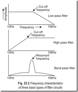
Just as there are circuits that generate sounds, there are also circuits that modify or “process” those sounds. Two of the most basic processors in common use are the amplifier and the filter. The amplifier is extremely valuable in electronic music because it controls the dynamic aspect–crescendo and diminuendo of a sound. The filter is a somewhat more complex circuit. It is an amplifier that controllablyrestricts the frequency response in one of three ways.
As a low-pass filter, it can cut off the high end of the audio spectrum. The high pass configuration can be used when it is desired to cut off the low end of the spectrum. When both ends of the spectrum are to be cut off, a bandpass filter is used. As shown in Fig. 25.2, the cutoff frequency of a low-pass filter or a high -pass filter is the frequency at which the filter starts to attenuate the signal, while the resonant frequency of a bandpass filter is the frequency at which the greatest amount of boost (or minimum amount of cut) is present.
Because the timbre of a sound depends largely on its harmonic content and since the desired harmonic content lies above the fundamental frequency of a signal, variable-cutoff low-pass filters that selectively attenuate certain overtones are used for modifying the timbre of various waveforms.
VOLTAGE CONTROL
With the oscillator, amplifier, and filter, a sound can be specified according to waveform, pitch, timbre and dynamic level. But without voltage control, a system consisting of these three building blocks has serious limitations. By using voltage control, the major parameters of the building blocks are made to respond to a dc or an ac voltage.
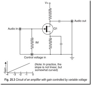
A voltage-controlled oscillator (VCO) has its pitch controlled not by turning a potentiometer, but by applying to it a control voltage .The cutoff frequency of a filter (VCF) or the gain of an amplifier (VCA) can be similarly controlled by a variable dc voltage.
For example, the amplifier shown in Fig. 25.3 has a conventional audio input but instead of using a potentiometer level control, a voltage is applied to input to control the gain. A 4 volt potential is sufficient to cut off Q1 and reduce the gain to zero. By slowly making the control voltage less negative, the gain will increase until the amplifier is operating at full gain at 0 volt. (In the oscillators used in Moog and ARP synthesizers, a 1 volt change in control voltage causes a one-octave jump in frequency; so, by applying stepped increments of 1/12 of a volt, the 12 tones of a conventional musical scale can be generated).
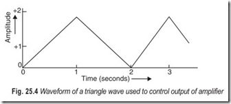
Because it requires much technique to precisely specify frequency, amplifier gain, etc. simply by having the musician turn a potentiometer, most electronic music composers rely on voltage control to perform complex pitch, amplitude, and timbre changes. As a result, specialised circuits designed solely to generate control voltages have come into being. For example, a sub-audio triangle wave of, say, 0.5 Hz makes an excellent control voltage. For one second, the signal rises to peak amplitude (2 volts in Fig. 25.4). Then for another second it tapers off to zero amplitude. Applied to a voltage-controlled amplifier, this signal would be heard at the output as a linear increase and decrease of equal duration in each direction.
The common tremolo circuit found in guitar amplifiers and organs is simply a sine wave-controlled VCA. Vibrato is generally a VCO that is controlled by a 6 Hz or so sine wave. Of course any waveform can be used to control a voltage-controlled system, but the problem with using only oscillators to generate the control voltages is that sometimes a non-repeating waveform is desired. This problem is overcome with the aid of an envelope generator, a device that can produce a control voltage with specified rise, on, and fall times.
ENVELOPE GENERATOR
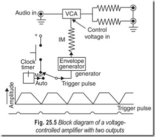
The timbre gate, when broken down into a block diagram, can be illustrated as shown in Fig. 25.5. It consists of a voltage-controlled amplifier with an audio input and two audio outputs. An envelope generator with adjustable rise, on, and fall times generates the control voltage for the VCA.
The envelope generator can be triggered manually or automatically to generate an envelope. The automatic triggering unit furnishes pulses that initiate the envelope. (Sometimes this type of pulse control system is referred to as a clock or a timer circuit). Because of this timed feature, periodic control voltages of an unusual shape can be generated.
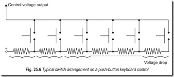
Although there are many types of control voltage generators, one of the most popular is the keyboard. It furnishes a string of control voltages to a control input with the various voltages selected by push button or key switches (see Fig. 25.6). In most commercial synthesizer keyboards, a pulse output is also available whenever a key is closed.
OTHER SIGNAL MODIFIERS
A system containing voltage-controlled oscillators, filters, and amplifiers represents a sophisticated electronic music setup. But there are other signal modifiers that are useful for specific functions and add a great deal of versatility to an electronic music studio. Some of these are:
Reverberators that artificially delay and decay a signal to simulate the effect of a sound bouncing off the walls of a large room. This effect can be accomplished in several ways but generally it is done by feeding the signal through springs or metal sheets coupled at both ends with special transducers.
Tape echo, a very precisely controlled delay system, bestows a sense of spaciousness, delay or repetition upon electronic music. It also permits a musician to “accompany” himself.
Ring modulators have two inputs, one for an audio signal and another for a modulating (or carrier) signal. At the output of the modulator appears the algebraic sum of the input frequencies, but both original signals are suppressed.
Fuzztones and waa-waa’s are also used as electronic modifies. The fuzztone generates harmonics from a signal with otherwise low harmonic content. The waa-waa is a variable-bandpass filter, its resonant frequency is controlled by a footpedal.
Mixers are not processors, but they are often used to adjust two ore more signal levels to suitable proportions. They are also useful for adding together control voltages when control by more than one waveform is desired. Mixers can be sophisticated multi-input devices containing echo buses, switchable reverberation, filtering arrangements, and other convenience features.
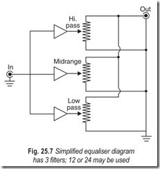
Equalisers are basically batteries of filters that cover various parts of the audio spectrum, each output terminating in a level control. A simplified equaliser diagram is shown in Fig. 25.7. Here, only three filters are shown, but equalisers that divide the spectrum into 12 or 24 bands are not uncommon.
Compressors and limiters are functionally related to each other. The limiter’s job is to maintain the maximum signal amplitude to a desired peak level. A compressor limits the peak amplitude of a signal but it also raises the low-level portions of the signal. When used with moderation, limiting and compression are hardly noticeable. However, with extreme limiting or compression, highly unusual effects are obtained.
ASSEMBLING A SYNTHESIZER
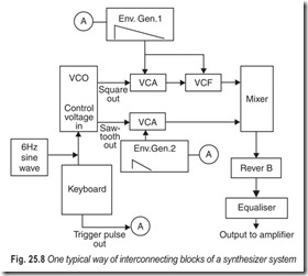
A modern synthesizer contains most of the building blocks mentioned above. To give an idea of how these blocks might be put together to make a sound, Fig. 25.8 shows in block diagram form a representative method of interconnection (traditionally with the aid of patchcords). The heart of the system is the VCO, its frequency determined primarily by the control voltage from the keyboard. By properly tuning the keyboard, it is possible to generate a chromatic scale. In addition, a 6 Hz sub-audio sine wave control voltage vibrato modulates the primary frequency.
The master VCO has both square and sawtooth outputs. An envelope generator delivers a control voltage to a VCA and a VCF. This combination modifies the square wave. The sawtooth wave is processed by an envelope generator/VCA combination. Both waveforms, after being modified, are mixed down to one output, given some reverberation, and equalised to emphasise or cut any specific frequency components.
Striking a key initiates several events. First, a control voltage is applied to the VCO to generate a tone of specific pitch. Simultaneously, a pulse triggers the two envelope generators. Envelope generator 1 is set for a long decay, while generator 2 is set for a short decay. By controlling a VCF, envelope generator 1 also changes the harmonic content of the square wave so that, as the signal decays, overtones are removed. The overall effect is a note of a certain pitch, modulated by vibrato, whose attack is mainly a burst of sawtooth waves followed by a slowly decaying square wave, the timbre of which changes as it decays.
Changing any part of the system yields a radically different sound. Any subtle changes can give dramatically different results. This is perhaps why so many people refer to electronic music as a medium of infinite potential. There are so many building blocks and their possible combinations so numerous that the problem for many composers is not what sounds to make, but what sounds not to make.
EXERCISES
Descriptive Questions
1. What forms the basis of electronic music synthesis?
2. What are the basic modifiers of sound?
3. Explain the significance of voltage control.
4. Briefly explain the working of an envelope generator.
5. What are the different signal modifiers?
6. How will you assemble a synthesizer?
Multiple Choice Questions
1. Sine wave is harmonically
(a) the least complex of waveforms (b) the most complex of waveforms
2. A triangle wave contains a number of
(a) even harmonics (b) odd harmonics
3. White noise generator generates a wave that
(a) contains all possible frequencies
(b) does not contain all possible frequencies
(c) contains harmonically related frequencies
(d) is a pure sine wave of continuously variable frequency
4. A low pass filter can cut
(a) the lower end of the audio spectrum
(b) the higher end of the audio spectrum
5. When both ends of the spectrum are to be cut
(a) a low pass filter is used (b) a high pass filter is used
(c) a band pass filter is used
6. In the oscillators used in Moog and ARP synthesizers a 1 volt change in control causes
(a) a one-octave jump in frequency (b) a two-octave jump in frequency
(c) a three-octave jump in frequency
Fill in the Blanks
1. The higher the frequency, or harmonic, the…………………………………… the amount of energy it receives.
2. In a voltage controlled amplifier a…………………………………… is applied to the input to control the gain.
3. The common circuit found in guitar or amplifiers is simply a…………………………………… controlled VCA.
4. Waveforms with generous amounts of harmonics are…………………………………… to modify.
5. Variable cut off…………………………………… are used of modify the timbre of various waveforms.
6. Changing any part of a synthesizer yields a…………………………………… different sound.
ANSWERS
Multiple Choice Questions
1. (a) 2. (b) 3. (a) 4. (b) 5. (c) 6. (a)
Fill in the Blanks
|
1. smaller |
2. voltage |
3. sine wave |
|
4. easy |
5. low-pass filters |
6. radically |
