Steel Wire Armour Cables
These cables offer very good mechanical protection. They are known simply as SWA cables. The full name for the type used in this course is XLPE / SWA / PVC. This means that the conductors are insulated by XLPE, there is a layer of steel wire protecting those conductors and there is an overall PVC sheath to complete the cable. It is still possible to get PVC insulated SWA. Its full name is PVC / SWA / PVC.
Construction
The conductors in these cables are made of copper or aluminium. Copper conductor are stranded ( except the smaller sizes ). Aluminium conductors are solid. These conductors are often sector-shaped to fit together more closely. There is a filling compound around the insulated conductors to produce a circular shape. A layer of steel wire or tape is wrapped around this filling compound. The steel armouring protects the cable from mechanical damage whilst in service. The use of the steel armour as the “protective conductor” is limited, see ETCI Rules. It also provides strength to withstand handling during installation.
A soft bedding of jute or other suitable material is sometimes applied over the internal sheath to serve as a base for the steel armour.
Application of SWA Cable
SWA cable is suitable for permanent wiring on the surface. It may be used outside and is suitable for burial directly in the ground. It is primarily intended for use in industrial premises. SWA cables have a wide range of applications, some of which are listed below:
· Heavy sub-main distribution.
· Underground electrical supplies.
· Circuit wiring in environments, where there is a likelihood of mechanical damage.
XLPE insulated cable is suitable for use in any temperature between -25°C and +80°C. Some manufacturers state that it is suitable down to -40°C.
Installation of SWA Cables
SWA cable can be laid directly in the ground, in ducts or fixed directly onto walls using cable clips. If several cables are to follow the same route they may best be supported on a cable tray or rack system.
· It is not always possible to use the armour as the “sole protective conductor”
· Where the armour is not used as a protective conductor it must still be earthed
· Must be terminated using a gland
The resistance of the steel wire armour is much higher than that of copper therefore a larger CSA of steel wire is required to comply with the ETCI Rules. The CSA of the steel wire armour in some cable sizes is adequate, while in others it is not. Manufacturers are now including a separate core, insulated Green / Yellow for this reason. Otherwise a separate Green / Yellow cable will have to be installed alongside the SWA cable. The minimum internal bend radius is found by multiplying the overall diameter of the cable by a factor of 8. SWA cable should not be worked below 0°C.
Terminating SWA Cable
Where possible the gland should be fixed in the cable entry and the cable then installed through the gland. Good contact must be achieved between the cable armour and earth. A bonding ring is essential for this purpose when terminating SWA into a non-metallic enclosure. Bends close to the gland should be formed before stripping the cable.
Note: Some consultant engineers require a bonding ring at every SWA termination.
If SWA cable is used to connect directly to a motor, a loop should be formed in the cable adjacent to the motor to permit any necessary adjustments and allow for vibration.
Listed below are the steps to be followed when terminating an SWA cable:
· Fix gland in position in enclosure and tighten well ( Use a spanner, not a pipe grips )
· Fit shroud ( if required ) and gland nut over cable
· Decide the point to which the armour must be removed
· Cut half-way through the armour wires at this point using a hacksaw
· Remove cable sheath to same point
· Remove armour wires by bending at point where cut by saw
· Remove outer sheath to expose a short section of armour ( twice length of gland cone )
· Move inner core in a circular outward motion to fan out the armour
· Remove required length of internal sheath ( must protrude 5-10 mm beyond the gland into the enclosure to protect the insulation )
· Enter cable into gland and ensure that all armour wires pass outside the gland cone
· Tighten gland nut over armour wires ( Use a spanner, do not over tighten )
· Fit shroud over gland ( only if required )
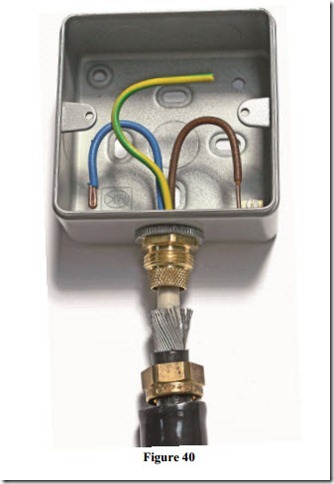
Figure 40 shows a 3 x 2.5 SWA cable being terminated into a surface mounted metal socket box, using a BW 20S brass gland. This gland is suitable for use in dry locations. The steel wires are fanned out to allow them fit over the cone of the gland. The gland nut and shroud are in position, ready for use.
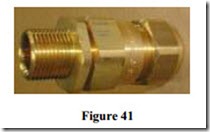
Figure 41 shows a CW 20S brass gland for use in wet locations. It provides a water tight seal around the outer sheath of the cable. A watertight seal must also be provided where the gland is fixed to the enclosure.
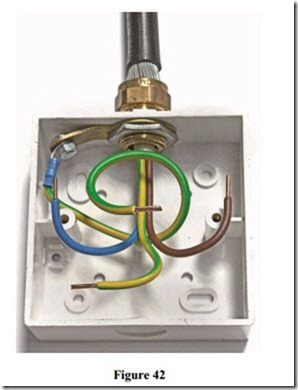
Figure 42 shows a 3 x 2.5 SWA cable being terminated into a surface mounted plastic switch / socket box, using a 20S brass gland and a bonding ring. The connection to the steel wire is made via the bonding ring.


