Solid-state device technologies, which are available to the amplifier designer, fall, broadly, into three categories: bipolar junction transistors (BJTs) and junction diodes; junction field effect transistors (FETs); and insulated gate FETs, usually referred to as MOSFETs (metal oxide silicon FETs), because of their method of construction. These devices are available in both P type—operating from a negative supply line—and N type—operating from a positive supply line. BJTs and MOSFETs are also available in small-signal and larger power versions, whereas FETs and MOSFETs are manufactured in both enhancement- mode and depletion-mode forms. Predictably, this allows the contemporary circuit designer very considerable scope for circuit innovation, by comparison with electronic engineers of the past, for whom there was only a very limited range of vacuum tube devices.
In addition, there is a very wide range of integrated circuits (ICs), which are complete functional modules in some (usually quite small) individual packages. These are designed both for general-purpose use, such as operational amplifiers, and for more specific applications, such as voltage regulator devices, current mirrors, current sources, phase-sensitive rectifiers, and an enormous variety of designs for digital applications, which mostly lie outside the scope of this book.
In the case of discrete devices, I think it is unnecessary for the purposes of audio amplifier design to understand the physical mechanisms by which the devices work, provided that their would-be user has a reasonable grasp of their operating characteristics and limitations and, above all, a knowledge of just what is available.
Junction Transistors
These are nearly always three-layer devices, fabricated by the multiple and simultaneous vapor phase diffusion and etching of small and intricate patterns on a large, thin slice of very high purity single crystal silicon. A few devices are still made in germanium, mainly for replacement purposes, and some VHF components are made in gallium arsenide, but these will not, in general, lie within the scope of this book. The fabrication techniques may be based on the use of a completely undoped (intrinsic) slice of silicon, into which carefully controlled quantities of impurities are diffused through an appropriate mask pattern from both sides of the slice. These are described in the manufacturers’ literature as double diffused, triple diffused, and so on.
In a later technique, evolved by the Fairchild Instrument Corporation, all the diffusions were made from one side of the slice. These devices were called planar and had, normally, a better HF response and more precisely controlled characteristics than, for example, equivalent double-diffused devices. In a further, more recent, technique, also due to Fairchild, the silicon slice will have been made to grow a surface layer of uniformly doped silicon on the exposed side (which will usually form the base region of a transistor) and a single diffusion was then made into this doped layer to form the emitter junction. This technique was called epitaxial and led to transistors with superior characteristics, especially at HF. Since this is the least expensive BJT fabrication process, it will normally be used wherever it is practicable, and if no process is specified it may reasonably be supposed to be a planar-epitaxial type.
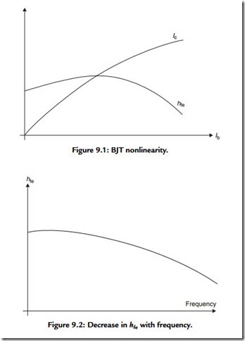
In contrast to a thermionic valve, which is a voltage-controlled device, the BJT is a current operated one. So while a change in the base voltage will result in a change in the collector current, this has a very nonlinear relationship to the applied base voltage. In comparison to this, the collector current changes with the input current to the base in a relatively linear manner. Unfortunately, this linear relationship between Ic and Ib tends to deteriorate at higher base current levels, as shown in Figure 9.1. This relationship between base and collector currents is called the current gain, and for AC operation is given the term hfe, and its nonlinearity is an obvious source of distortion when the device is used as an amplifier. Alternatively, one could regard this lack of linearity as a change of hFE (this term is used to define the DC or LF characteristics of the device) as the base current is changed. A further problem of a similar kind is the change in hfe as a function of signal frequency, as shown in Figure 9.2.
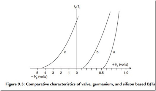
However, as a current amplifier (which generally implies operation from a high impedance signal source) the behavior of a BJT is vastly more linear than when used as a voltage amplifying stage, for which the input voltage/output current relationships are
shown for an NPN silicon transistor as line ‘a’ in Figure 9.3. (I have included, as line ‘b’, for reference, the comparable characteristics for a germanium junction transistor, although this would normally be a PNP device with a negative base voltage, and a negative collector voltage supply line.) By comparison with, say, a triode valve, whose anode current/grid voltage relationships are also shown as line ‘c’ in Figure 9.3, the BJT
is a grossly nonlinear amplifying device, even if some input (positive in the case of an NPN device) DC bias voltage has been chosen so that the transistor operates on a part of the curve away from the nonconducting initial region.

