Amplifier Coupling
To obtain greater amplification, transistor amplifiers may be connected together. However, to prevent one amplifier’s bias voltage from affecting the operation of the second amplifier, a coupling technique must be used. The coupling method used must not disrupt the operation of either circuit. Coupling methods used include resistance-capacitance coupling, impedance coupling, transformer coupling, and direct coupling.
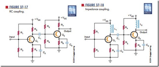
Resistive-capacitive coupling, or RC coupling, consists of two resistors and a capacitor connected as shown in Figure 37-17. Resistor R3 is the collector load resistor of the first stage. Capacitor C1 is the DC-blocking and AC-coupling capacitor. Resistors R5 and R6 are the input load resistor and DC return resistor for the base-emitter junction of the second stage. Resistance-capacitive coupling is used primarily in audio amplifiers.
Coupling capacitor C1 must have a low reactance to minimize low-frequency attenuation. Typically, a high-capacitance value of 10 to 100 microfarads is used. The coupling capacitor is generally an electro- lytic type.
The reactance of the coupling capacitor increases as the frequency decreases. The low-frequency limit is determined by the size of the coupling capacitor. The type of transistor used determines the high-frequency limit.
The impedance-coupling method is similar to the RC-coupling method, but an inductor is used in place of the collector load resistor for the first stage of amplification (Figure 37-18).
Impedance coupling works just like RC coupling. The advantage is that the inductor has a very low DC resistance across its windings. The AC output signal is developed across the inductor just as across the load resistor. However, the inductor consumes less power than the resistor, increasing the overall efficiency of the circuit.
The disadvantage of impedance coupling is that the inductance reactance increases with the frequency. The voltage gain varies with the frequency. This type of coupling is ideal for single-frequency amplification when a very narrow band of frequencies must be amplified.
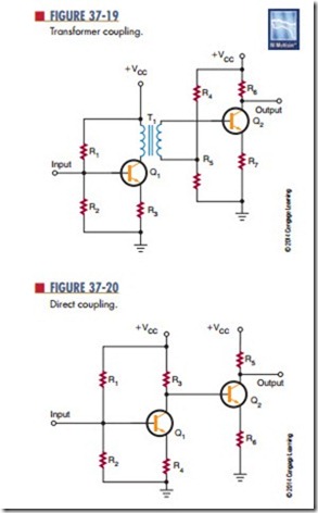
In a t ransfor mer-couple d circuit, t he two amplifier stages are coupled through the transformer (Figure 37-19). The transformer can effectively match a high-impedance source to a low-impedance load. The disadvantage is that transformers are large and expensive. Also, like the inductor-coupled amplifier, the transformer-coupled amplifier is useful only for a narrow band of frequencies.
When very low frequencies or a DC signal must be amplified, the direct-coupling technique must be used (Figure 37-20). Direct-coupled amplifiers provide a uniform current or voltage gain over a wide range of frequencies. This type of amplifier can amplify frequencies from 0 (DC) hertz to many thousands of
hertz. However, direct-coupled amplifiers find their best applications with low frequencies.
A drawback of direct-coupled amplifiers is that they are not stable. Any change in the output current of the first stage is amplified by the second stage. This occurs because the second stage is essentially biased by the first stage. To improve the stability requires the use of expensive precision components.
Questions
1. What are the four methods for coupling amplifiers?
2. Where would RC coupling be used?
3. What determines low-frequency and high- frequency coupling?
4. Why would impedance coupling be used over RC coupling?
5. What is the drawback of using direct-coupled amplifiers?

