This chapter covers some of the important test equipment used to take various AC measurements.
AC Meters
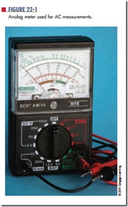
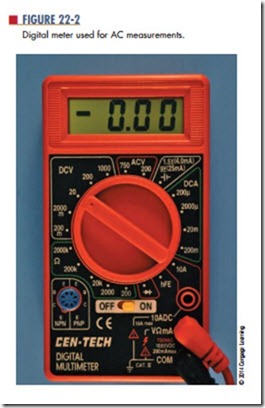
The moving coil meter movement is referred to as the d’Arsonval meter movement. The analog meter (Figure 22-1) is a moving coil meter. The easy-to-read digital meter (Figure 22-2) has recently replaced the analog meter.
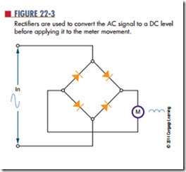
Moving coil meters are designed to measure DC current. To measure AC current on this meter, the AC current must first be converted to DC current. This is accomplished with diodes called rectifiers. The process of converting AC to DC is called rectification. The rectifiers are placed between the meter input and
the meter movement and allow current to flow in only one direction (Figure 22-3). The rectifiers convert the sine wave into a pulsating DC current that is applied to the meter movement.
■ FiguRE 22-3
Rectifiers are used to convert the AC signal to a DC level before applying it to the meter movement.
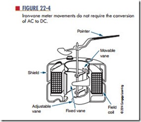
A second type of AC meter uses the iron–vane meter movement (Figure 22-4). This does not require the conversion of AC to DC. It consists of two iron vanes located within a coil: One vane is stationary and the other is movable. A pointer is attached to the movable vane and moves proportionally to the current passing through the coil. The magnetic field of the coil induces a north and south pole into the iron vanes. Because like poles repel and both vanes have the same polarity, they move away from each other. The iron- vane movement requires more current for a full-scale deflection than does the moving coil meter movement. For this reason, iron-vane movements find little appli- cation in low-power circuits. The iron-vane movement is also inaccurate for frequencies above 100 hertz. It is used primarily for 60-hertz applications.
The clamp-on meter is based on the principle that an AC current flowing in a conductor causes a magnetic field to expand and collapse as the current increases and decreases in value (Figure 22-5). Each time the AC current changes polarity, the magnetic field changes direction. The clamp-on AC meter uses a split- core transformer that allows the core to be opened and placed around the conductor. At the end of the core is a coil, which is cut by the magnetic lines of force. This induces a voltage into the coil, creating a flow of alter- nating current. This AC current must be rectified before being sent to the meter movement, generally a moving coil. This type of meter is used for measuring high val- ues of AC current. The current in the conductor must be large in order to produce a magnetic field strong enough to induce a current flow in the core of the meter.
suring device. However, this type of meter movement can also be used to measure AC voltage and power. Because alternating current changes direction periodically, the meter leads can be hooked into an AC circuit in either direction.
C A u t i o n !
The meter must be connected in series with the circuit when measuring current. When measuring voltage, the meter must always be connected in parallel.
Always be sure the current or voltage being measured is within the range of the meter. For additional protection, always start at the highest scale and work down to the appropriate scale.
Questions
1. How is a d’Arsonval meter movement used to measure an AC voltage?
2. What makes an iron-vane meter movement desirable for measuring an AC signal?
3. Explain the principle behind a clamp-on AC meter.
4. Draw a circuit showing how to connect an AC ammeter.
5. Describe the proper procedure for using an AC voltmeter in a circuit. (Include switch settings where possible.)


