 IMPEDANCE TRANSFORMATION THROUGH A TRANSFORMER
The impedance of a device is defined as the ratio of the phasor voltage across it to the phasor current flowing through it.
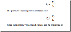
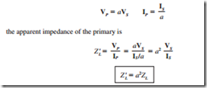
Since a transformer changes the current and voltage levels, it also changes the impedance of an element. The impedance of the load shown in Fig. 3.3b is
It is possible to match the magnitude of load impedance to a source impedance by simply selecting the proper turns ratio of a transformer.
Related posts:
Transformer,three phase:Instrument Transformers
POWER STATION ELECTRICAL SYSTEMS AND DESIGN REQUIREMENTS:ELECTRICAL SYSTEM DESCRIPTION
INDUSTRIAL CONTROL:OUTPUT DEVICES
Instrumentation techniques:Digital to analogue conversions
GENERATOR INSPECTION AND MAINTENANCE:ON-LOAD MAINTENANCE AND MONITORING
Electric Motor Manual – SELECTION AND APPLICATION – Effect of motor efficiency on energy...
AIRGAP FIELD SPACE HARMONICS, PARASITIC TORQUES, RADIAL FORCES, AND NOISE
Speed control of d.c. Motors:Thyristor Controller Starters
Transformer:Simplified Diagram
Speed control of d.c. Motors:Thyristor Speed Control of Separately-excited D.C. Motor
Synchronous Motor:Effect of Excitation on Armature Current and Power Factor
Alternators:Maximum Power Output
Functions of Motor Control:Selector Switches
AC Servo Motors:Frequency Converter

