Electrophotographic printing technology
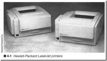
ELECTROPHOTOGRAPHIC (EP) PRINTERS ARE DIFFERENT fundamentally from the other types of printers discussed in Chapter 3. Those “conventional” printers develop dots as a one-step process using impact, heat, or ink. EP printers are not nearly as simple (figure 4-1). Images are formed by a complex and delicate interaction of light, static electricity, chemistry, pressure, and heat , all guided by a sophisticated ECU. This chapter shows you the operation and intricacies of EP operation.
The classical electrophotographic approach
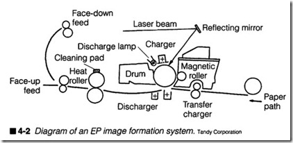
Electrophotographic printing is accomplished through a “process” rather than a “print head.” The collection of components that per forms the EP printing process is called an Image Format ion Sys tem (or IFS). An IFS is made up of eight distinctive areas: a photosensitive drwn, cleaning blade, erasure lamp, primary corona, writing mechanism, toner, transfer corona, and fusing rollers. Each
of these parts, as shown in figure 4-2, play an important role in the proper operation of an IFS. Trouble in any of these areas will ad versely effect the printed output.
A photosensitive drum is generally considered to be the heart of any IFS. An extruded aluminum cylinder is coated with a nontoxic organic compound that exhibits photoconductive properties. That is, the coating will conduct electricity when exposed to light. You might see this referred to as organic photoconductive chemicals (or OPC). The photosensitive compound gives the EP drum a bright green appearance. The aluminum base cylinder is connected to ground of the high-voltage power supply; this is an important point, serious printing problems can occur if the ground becomes loose.
It is the drum that actually receives an image from a writing mech anism, develops the image with toner, then transfers the developed image to paper. Although you might think that this constitutes a print head because it delivers an image to paper, the image is not yet permanent; other operations must be performed by the IFS. Complete image development is a six-step process that involves all eight IFS components: cleaning, charging, writing, developing, transfer, and fusing. To really understand the IFS, you should know each of these steps in detail. The following sections of this chapter show you how each part of the IFS works together.
Cleaning
Before a new printing cycle can begin, the photosensitive drum must be physically cleaned and electrically erased (typically re ferred to as conditioning). Cleaning might sound like a rather unimportant step, but not even the best drum will transfer every microscopic granule of toner to a page every time. A rubber clean ing blade is applied across the entire length of the drum to gently scrape away any residual toner that might remain from a previous image (figure 4-3). If residual toner were not cleaned, it could ad here to subsequent pages and appear as random black speckles. Toner that is removed from the drum is deposited into a debris cavity. Keep in mind that cleaning must be accomplished without scratching or nicking the drum. Any damage to the photosensitive surface would become a permanent mark that appears on every subsequent page. Some EP printer designs actually return scrap toner back to the supply for reuse. This kind of recycling tech nique can substantially extend the life of your electrophotographic cartridge, and eliminate the need for a large debris cavity.
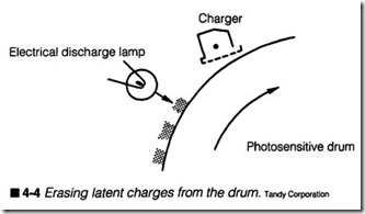
Images are written to a drum’s surface as horizontal rows of elec trical charges, which correspond to the image being printed. A dot of light causes a relatively positive charge at that point. This cor responds to a visual dot in the completed image. Absence of light allows a relatively negative charge to remain and no visible dots are generated. All drum charges caused by light MUST be re moved (or discharged) before any new images can be written; oth erwise images would overwrite and superimpose on one another. A series of erasure lamps are placed in close proximity to the drum’s surface as shown in figure 4-4. Their light is carefully fil tered to allow only effective wavelengths to pass. Erase light bleeds away any charges along the drum. Charges are carried to ground through the aluminum cylinder. After erasure, the drum’s surface is completely neutral; it contains no charges at all.
Charging
A neutral drum surface is no longer receptive to light from the writing mechanism. New images cannot be written until the drum is charged again. In order to condition the drum, a uniform elec trical charge must be applied evenly across its entire surface. Sur face charging is accomplished by applying a tremendous negative voltage (often about -6,000V) to a solid wire called a primary corona located close to the drum. Since the drum and high-voltage power supply share the same ground, a powerful electrical field is established between the corona wire and drum, as in figure 4-5.
For low voltages, the air gap between a corona wire and drum would act as an insulator. With thousands of volts of potential, however, the insulating strength of air breaks down and an electric corona forms. A corona ionizes any air molecules surrounding the wire, so negative charges migrate to the drum’s surface. A corona also breaks down air into ozone, which must be filtered and ex hausted from the printer assembly.
The trouble with ionized gas is that it exhibits a very low resis tance to current flow. Once a corona field is established, there is essentially a “short-circuit” between the wire and drum. This is not good for a high-voltage power supply. A primary grid (part of the primary corona assembly) is added between the wire and drum. By applying a negative voltage to the grid, charging voltage and current to the drum can be carefully regulated. This “regulat ing grid voltage” (often -600 to -l,OOOV) sets the charge level ac tually applied to the drum. Image intensity can be adjusted to an extent by varying the grid voltage generated by the high-voltage power supply. The drum is now ready to receive a new image.
Writing
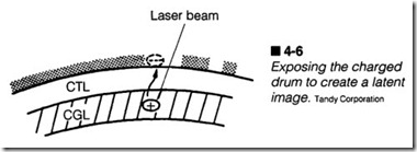
In order to form a latent image on a drum surface, the uniform charge that has conditioned the drum must now be discharged in the precise areas where images are to be produced. Images are written to the drum using light as shown in figure 4-6. Any points on the drum exposed to light will discharge to a very low level (about -1OOV), while any areas left unexposed retain their condi tioning charge. The device that produces and directs light to the drum surface is called a writing mechanism.
Because images are formed as a series of individual dots, a larger number of dots (per unit area) will allow finer resolution of the im age, and generally higher quality. For example, suppose a writing mechanism can place 300 dots per inch along a single horizontal line on the drum, and the drum can rotate in increments of Y.!OO of an inch. This means your printer can develop images with a reso lution of 300 x 300 dots per inch (DPI). Current EP printers are
providing resolutions of 600 x 600 dpi and 1,200 x 1,200 dpi. Lasers have been traditionally used as writing mechanisms, and are still used in many EP printer designs, but new printers are re placing lasers with bars of light-emitting diodes (LEOs) to direct light as needed. Writing mechanisms are covered more extensively later in this chapter.
Developing
Images written to the drum are initially invisible, merely an array of electrostatic charges. The latent image must be “developed” into a visible one before it can be transferred to paper. Toner is used for this purpose. Toner itself is an extremely fine powder of plastic resin and organic compounds bonded to iron particles. In dividual granules can be seen under extreme magnification of a microscope.Toner is applied using a transfer roller in a developer unit as shown in figure 4-7. A transfer roller is basically a long metal sleeve containing a permanent magnet. It is mounted inside the toner supply trough. When the cylinder turns, iron in the toner at tracts it to the cylinder. Once attracted, toner acquires a negative static charge provided by the high-voltage power supply. This static charge level is typically equal to the drum’s charge level (about
-600V). A restricting blade (called a doctor blade) limits toner on the cylinder to just a single layer.
Charged toner on the transfer roller now rotates into close prox imity with the exposed drum. Any points on the drum that are not exposed will retain a strong negative charge. This repels toner,
which remains on the toner cylinder and is returned to the supply. Any points on the drum that are exposed now have a much lower charge than the toner particles (about -IOOV). This attracts toner from the cylinder to corresponding points on the drum. Toner “fills in” the latent image to form a visible (or developed) image.
In actual practice, an ac booster bias is added in series to the de in tensity bias on the transfer roller. The ac causes fluctuations in the toner’s charge level. As the ac signal goes positive, the intensity level increases to help toner particles overcome attraction of the cylinder’s permanent magnet. As the ac signal goes negative, in tensity levels decrease to pull back any toner particles that might have falsely jumped to unexposed areas. This technique greatly improves print density and image contrast. The developed image can now be applied to paper.
Transfer & discharge
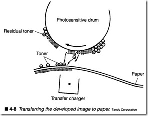
At this point, the developed toner image on the drum must be transferred onto paper. Because toner is now strongly attracted to the drum, it must be pried away by applying an even larger attrac tive charge to the page. A transfer corona wire charges the page as shown in figure 4-8. The theory behind the operation of a transfer corona is exactly the same as that for a primary corona, except that the potential is now positive. This places a powerful positive charge onto paper, which attracts the negatively charged toner
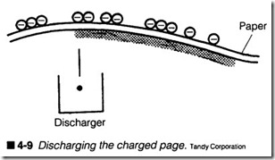
particles. Remember that transfer is not a perfect process. Not all toner is transferred to paper, which is why a cleaning process is needed.Caution is needed here. Because the negatively charged drum and positively charged paper tend to attract each other, it is possible that paper could wrap around the drum. Even though the small-di ameter drum and natural stiffness of paper tend to prevent wrap ping, a static charge eliminator (or static eliminator comb) is included to counteract positive charges and remove the attractive force between paper and drum as in figure 4-9. Paper now has no net charge. Another good reason for discharging the paper is to prevent charge irregularities from shifting the toner now applied on paper before fusing can take place. Also, discharging the paper will keep subsequent sheets from repelling each other when the sheets are ejected. The drum can be cleaned and prepared for a new image.
Fusing
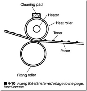
Once the toner image has reached paper, it is only held to the page by gravity and weak electrostatic attraction. Toner must be fixed permanently (or fused) to the page before it can be handled. Fus ing is accomplished with a heat and pressure assembly like the one shown in figure 4-10. A high-intensity quartz lamp heats a non stick roller to about 180°C. Pressure is applied with a pliable rub ber roller. When a developed page is passed between these two rollers, heat from the top roller melts the toner, and pressure from the bottom roller squeezes molten toner into the paper fibers where it cools and adheres permanently. The finished page is then fed to an output tray. Note that both rollers are referred to asfus ing rollers, e en though only the top roller actually “fuses.”
To prevent toner particles from sticking to a fusing roller, it is coated with a nonstick resin such as Teflon. A cleaning pad is added to scrape away any toner that might yet adhere. The pad also applies a thin coating of silicon oil to prevent further sticking. Fusing temperature must be carefully controlled. Often a thermis tor is used to regulate current through the quartz lamp in order to maintain a constant temperature. A snap-action thermal switch is also included as a safety interlock in the event that lamp tempera ture should rise out of control. If temperature is not controlled carefully, a failure could result in damage to the fusing assembly, or even a frre hazard.
Writing mechanisms
As discussed earlier in this chapter, the newly charged photosensi tive drum contains a uniform electrostatic charge across its sur face. To form a latent image, the drum must be discharged at any and all points that comprise the image. Directed light is used to discharge the drum as needed. Images are scanned onto the drum one horizontal line at a time. A single pass across the drum is called a trace or scan line. Light is directed to any points along the scan line where dots are required. When a scan line is completed, the drum increments in preparation for another scan line. It is up to the printer’s control circuits to break down an image into individ ual scan lines, then direct the writing mechanism accordingly.
Lasers
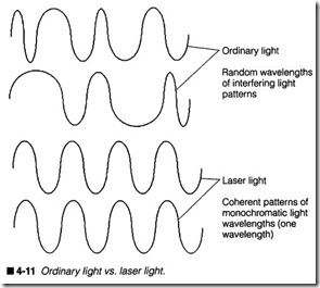
Lasers have been around since the early 1960s, and they have de veloped to the point where they can be manufactured in a great variety of shapes, sizes, and power output. To understand why lasers make such a useful writing mechanism, you must under stand the difference between laser light, and ordinary “white” lightas shown in figure 4-11.
Ordinary white light is actually not white. The light you see is com posed of many different wavelengths, each traveling in their own directions. When these various wavelengths combine, they do so virtually at random. This makes everyday light very difficult to di rect and almost impossible to control as a fine beam. As an exam ple, take a flashlight and direct it at a far wall. You will see just how much white light can scatter and disperse over a relatively short distance.
The nature of laser light, however, is much different. A laser beam contains only one major wavelength of light (it is monochromatic). Each ray travels in the same direction and combines in an additive fashion (known as coherence). These characteristics make laser light easy to direct at a target as a hair-thin beam, with almost no scatter (or divergence). Older EP printers used Helium-Neon CHeNe) gas lasers, but semiconductor laser diodes have essen tially replaced gas lasers in just about all laser printing applica tions.
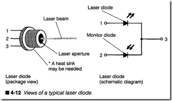
Laser diodes are very similar to ordinary light-emitting diodes as in figure 4-12. When the appropriate amount of voltage and cur rent is applied to a laser diode, photons of light will be liberated that have the characteristics of laser light (coherent, monochro matic, and low divergence). A small lens window (or laser aper ture) allows light to escape, and helps to focus the beam. Laser diodes are not very efficient devices; a great deal of power is re quired to generate a much smaller amount of light power, but this trade-off is usually worthwhile for the small size, light weight, and high reliability of a semiconductor laser.
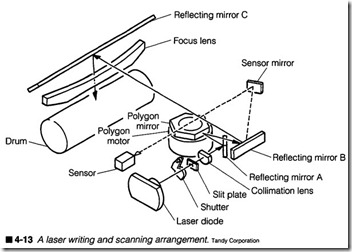
Generating a laser beam is only the beginning. The beam must be modulated (turned on and off) while being swept across the drum’s surface. Beam modulation can be accomplished by turning the laser on and off as needed (easily accomplished with fast semi conductor diodes), as shown in figure 4-13, or by interrupting a continuous beam with an electro-optical switch (typically used with gas lasers that are difficult to switch on and off rapidly). Mir rors are used to alter the direction of the laser beam, while lenses are used to focus the beam and maintain a low divergence at all points along the beam path. Figure 4-13 is just one illustration of a laser writing mechanism, but it shows some of the complexity that
is involved. The weight of glass lenses, mirrors, and their shock mountings have kept EP laser printers bulky and expensive.
Alignment has always been an unavoidable problem in complex optical systems such as figure 4-13. Consider what might happen to the beam if any optical component should become damaged or fall out of alignment; focus and direction problems could render a drum image unintelligible. Unfortunately, the realigrunent of opti cal systems is virtually impossible without special alignment tools, and is beyond the scope of this book. Finally, printing speed is lim ited by the speed of moving parts, and the rate at which the laser beam can be modulated.
LEOs
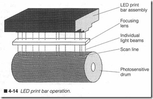
Fortunately, a photosensitive drum is receptive to light from many different sources. Even light from light-emitting diodes (LEDs) can expose the drum. By fabricating a series of microscopic LEDs into a single scan line, as shown in figure 4-14, an individual LED can be provided for every possible dot in a scan line. For example, the ROHM JE3008SS02 is an LED print bar containing 2,560 mi croscopic LEDs over 8.53 inches. This equates to 300 dots per
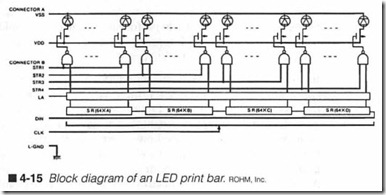
inch. Each LED is just 50 x 65 micrometers (J..Lm) and they are spaced 84.6 J..lffi apart.The operation of an LED print bar such as the one shown in figure 4-15 is remarkably similar to that of a thermal line-print head dis cussed in Chapter 3. An entire series of data bits corresponding to each possible dot in a horizontal line is shifted into internal digital circuitry within the print bar. Dots that will be visible are repre sented by a logic “1,” and dots that are not visible will remain at logic “0.” For a device such as the JE3008SS02, 2,560 bits must be entered for each scan line.
After a complete line of data has been loaded through the DIN pin, the LEDs must be fired. This is performed in segments to reduce the power surges that would be generated if every LED were fired
together. The JE3008SS02 is divided into four segments of 640 dots. A trigger signal (or strobe) can be applied to STR1 through STR4. This passes data to each segment’s driver circuits. LEDs that illuminate will leave latent points on the drum’s surface. LEDs that do not light will have no effect. Each strobe is fired sequen tially until all four segments have been strobed. All 2,560 dots can be scanned in under 2.5 milliseconds (ms). The drum is incre mented oo of an inch, and a new scan line can be loaded into the print bar.
You can probably see the advantages of an LED print bar system over a laser approach. There are no moving parts involved in light delivery, no mirror motor to jam or wear out. The printer can op erate at much higher speeds because it does not have to overcome the dynamic limitations of moving parts. There is only one focus ing lens between the print bar and drum. This greatly simplifies the optics assembly, and removes substantial weight and bulk from the printer. An LED system overcomes almost all alignment prob lems, so a defective assembly can be replaced or aligned quickly and easily.
The electrophotographic cartridge
Electrophotographic printers mandate the use of extremely tight manufacturing tolerances to ensure precise, consistent operation. A defect of only a few thousandths of an inch could cause unac ceptable image formation. Even the effects of normal mechanical wear can have an adverse effect on print quality. Many key IFS components would have to be replaced every 5,000 to 10,000 pages to maintain acceptable performance. Clearly it would be un desirable to send your printer away for a complete (and time-con suming) overhaul every 10,000 pages.
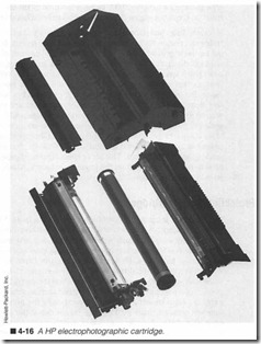
In order to ease manufacturing difficulties and provide fast, afford able maintenance to every EP printer user, critical components of the IFS, as well as a supply of toner, are assembled into a replace able electrophotographic cartridge. This is sometimes referred to as an engine. As figure 4-16 shows, a typical EP cartridge contains the toner roller, toner supply, debris cavity, primary corona (and primary grid), photosensitive drum, and cleaning blade assembly. All necessary electrical connectors and drive gears are included. By assembling sensitive components into a single replaceable car tridge, printer reliability is substantially improved by preventing problems before they ever become noticeable.
The complexity of an EP cartridge varies with the particular printer’s design . Some printers use a stand-alone engine, while providing sim ple, low-cost toner cartridges (usually with enough toner for several hundred prints). In these designs, the toner is cheap, but the re placement engine can be rather expensive (anywhere from $200 to $300 U.S.) and rated to last for tens of thousands of pages. An alter native to this approach, the more popular approach, is to integrate the toner cartridge and engine components into a single assembly. Hewlett-Packard’s engines (e.g., the 95A, 75A, 91A, and 98A) use this strategy. The major difference here is that the engine contains enough toner for 5,000 to 10,000 pages or more. So by the time toner runs out, the major engine components need to be replaced anyway.
You should also understand that the life expectancy of a toner/car tridge and engine are not absolute, but it will vary greatly depend ing on the way in which the printer is used. The amount of toner used will depend on the relative darkness of each page; pages with more black space use more toner, and vice versa. As an example, printers that produce complex graphics will tend to use toner faster. Because toner is largely an organic compound, it also suf fers from a limited shelf life. Most toner containers are marked with an expiration date, but once the toner/engine assembly is un sealed to the air, the toner should be used within six months. An other consideration is the engine components. Life expectancy (in pages) is typically defmed around standard 20-lb. xerography grade (photocopier) stock. Thicker or specially coated papers will tend to place more stress on the engine mechanics, which trans lates into shorter engine life.
Protecting an EP cartridge
As you might imagine, the precision components in an EP car tridge are sensitive and delicate. The photosensitive drum and toner supply are particularly sensitive to light and extreme envi ronmental conditions, so it is important to follow several handling and storage guidelines. First, the photosensitive drum is coated with an organic material that is extremely sensitive to light. Al though a metal shroud covers the drum when the cartridge is ex posed, light might still penetrate the shroud and cause unwanted exposure (also known asjogging). Deactivating the printer for a time will often eliminate mild fogging. Do not defeat the shroud in open light unless absolutely necessary, and then only for short pe riods. This will certainly fog the drum. A seriously fogged cartridge might have to be placed in a dark area for several days. Also, never expose the EP drum to direct sunlight; direct sunlight can perma nently damage the drum’s coating.
Next, avoid extremes of temperature and humidity. Temperatures exceeding 40°C can permanently damage an EP cartridge. Ex treme humidity is just about as dangerous. Do not allow the car tridge to become exposed to ammonia vapors or other organic solvent vapors; they break down the drum’s photosensitive coating very quickly. Finally, keep a cartridge secure and level. Never al low it to be dropped or abused in any way.
Finally, as the toner supply.diminishes, it might be necessary tore distribute remaining toner so that it reaches the toner roller. Be cause toner is available along the entire cartridge, it must be redistributed by rocking the cartridge back and forth along its long axis. If you tip a cartridge upright, remaining toner will fall to one end and cause uneven distribution. You should check the notes provides with your toner/engine cartridges for specific redistribu tion hints and precautions.
Refinements to the EP process
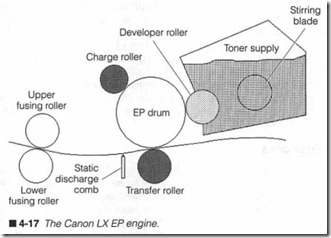
This chapter has focused largely on SX-type EP architecture used extensively in laser printers such as the Hewlett-Packard LaserJet II and III from 1986 through 1990. Since 1990, however, continu ing advances in EP design have simplified the electrophotographic process, while improving reliability. All of the basic principles have remain unchanged, but the process is more refined, as illustrated in figure 4-17.
Charge rollers
One of the first things you should notice is that the primary and secondary coronas have been eliminated and replaced with charge rollers. Introduced with the Canon LX EP engine in 1990, the charge rollers have replaced corona wires as a means of applying electrical charges to the EP drum and paper. The charge rollers themselves are little more than a specialized formulation of foam rubber, which accepts an even charge across its entire surface area (a key attribute for EP printers).
The main advantage to the charge rollers is the lower high-voltage requirement and the elimination of primary grid circuitry. While the primary corona demands about -6,000 V, the primary charging roller requires only about -1,000 V to achieve the required -600-V charge on the drum. This behavior also holds true for the transfer roller working at + 1,000 V and delivering a charge of +600 V to the page. A handy side effect to these lower charging voltages is a sig nificant reduction in the amount of ozone developed in the printer. Lower ozone eases environmental concerns about ozone health hazards.Unfortunately, a noted disadvantage to the charge roller scheme is that direct contact is required with the EP drum and page. In the ory, this is not a problem. But in practical applications, you cannot escape the dust, hair, pollen, and other airborne debris that will in variably fmd its way into the printer. Debris that collects on charge rollers has a chance of being transferred to the page (or interfer ing with the charge uniformity along the roller). Accumulations of foreign matter on the primary charge roller also stand a much greater chance of damaging the EP drum’s photosensitive coating. As it turns out, the transfer roller is more likely to attract foreign matter because of its lower physical position in the printer assem bly. To help keep the transfer roller clean, its charge is reversed when the printer is idle. Charge reversal tends to repel foreign matter off the roller.
Erase lamps
Another thing you will notice about figure 4-17 is that the erase lamps are missing. This is not an accident. With the introduction of charge rollers, the need for erase lamps disappeared. EP designers discovered that adding an ac signal to the de charging voltage on the primary charge roller effectively recharged the drum without any light exposure. Reports from the field indicate that the absence of erase lamps has made no visible difference in image quality.
Doctor blade
As discussed, a precise leveling blade (called a doctor blade) in the development unit serves to keep toner on the development roller limited to a single layer. As you might expect, any damage or misadjustment to the blade will have a pronounced effect on the image. Recent advances in materials have resulted in a rubber blade that actually rests on the development roller’s surface. This streamlines toner charging while still providing even toner distri bution on the roller.
New EP coatings
Traditionally, the photosensitive coating applied to an EP drum has been notoriously delicate; even the slightest nick or scratch left marks permanently in the drum. Over the last few years, EP coatings have improved dramatically in response to changing mar ket forces. One major reason for the improvements coincides with the introduction of charge rollers. Even a foam rubber roller in di rect contact with the EP drum demands a more durable photosen sitive coating. Another factor fueling the drum improvements is attributed to the growing remanufacturing market for toner car tridges and engines; drums are being expected to serve much longer lives as they are tested and recycled into remanufactured assemblies.
Toner paddle
One of the great complaints about toner supplies is that the toner is not always distributed evenly along the development roller. While this is not an issue while the toner is relatively new, a cartridge that is approaching exhaustion might experience faint streaks in the print where toner is particularly low. Newer toner/engine designs in clude a toner paddle that circulates the toner supply. This serves two important purposes: it keeps the toner from clumping, and it keeps the toner level steady across the development roller.
New toner
Even the toner itself has undergone some substantial improve ments over the last few years. Remember that toner is a microfine powder composed of plastic, iron, and coloring. As the resolution of an EP printer improves, the size of a toner granule becomes a gating issue. After all, a grain of toner must be smaller than a sin gle “dot,” otherwise, fine detail will be lost. Toner is continuing to improve in the remanufacturing market as well, but its overall quality still lags the original manufacturer’s toner.
