ASPIRATOR AIR SYSTEM
Chrysler Corp.
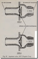
This system is used on 1977 Chrysler Corp. cata lyst equipped vehicles except 6-225, V8-360 ( 4 bar rel carb. with high altitude calibration) and Cali fornia. The valve in this system, Fig. 33, uses ex haust pressure pulsations to draw air into the exhaust system to reduce CO and HC emissions. It draws fresh air from the “clean” side of the air cleaner and past a one-way spring loaded dia phragm. The diaphragm opens to permit fresh air to mix with the exhaust gases during negative pres sure (vacuum) pulses. When the pressure is posi tive, the diaphragm closes and no exhaust gases are allowed to flow past the valve. The aspirator valve works most efficiently at idle and slightly above idle when the negative pulses are maximum. At higher engine speeds, the aspirator valve re mains closed.
AMERICAN MOTORS “ENGINE MOD” SYSTEM
This system controls exhaust emission levels by using composition cylinder head gaskets instead of steel gaskets and a special carburetor and dis tributor calibration. The carburetor incorporates idle limiters. The distributor centrifugal advance is calibrated to provide best performance and economy in the driving range and ignition timing is retarded only at idle speed (T.D.C.) to reduce exhaust emission levels at this ·slow engine speed. These engine modifications will result in a more complete combustion. Thermostatically controlled air cleaners are also used on most units to speed up engine warm-up.
AMERICAN MOTORS EXHAUST GAS RECIRCULATION (EGR)
The EGR system consists of a diaphragm actu ated flow control valve ( EGR valve), coolant tem perature override switch, low temperature vac uum signal modulator, high temperature vacuum signal modulator and connecting hoses.
The purpose of the EGR system is to limit the formation of oxides of nitrogen ( NOx) by diluting the fresh intake charge with a metered amount of exhaust gas, thereby reducing the peak tempera tures of the burning gases in the engine combus tion chambers.
EGRValve
The EGR valve is mounted on an machined surf ace at the rear of the intake manifold on V-8 engines and on the side of the intake manifold on six cylinder engines. The valve used with an automatic transmission is calibrated differently than the valve used with a manual transmission.
The valve is held in a normally closed position by a coiled spring located above the diaphragm. A special fitting is provided at the carbureto·r to route ported (above throttle) vacuum through hose connections to a fitting on the valve which is located above the diaphragm. A passage in the intake manifold directs exhaust gas from the ex haust crossover passage ( V8 engine) or from be low the riser area (six cylinder engine) to the EGR valve. When the diaphragm is actuated by vacuum, the valve opens and meters exhaust gas through another passage in the intake manifold to the floor of the manifold below the carburetor.
Coolant Temperature Override Switch
This switch is located at the coolant passage of the intake manifold (adjacent to oil filler tube) on a V8 engine or at the left side of the engine block (formerly the drain plug location) on a six cylin der engine. The outer port of the switch is open and not used. The inner port is connected by a hose to the EGR fitting at the carburetor. The center port is connected to the EGR valve.
When the coolant temperature is below ll5° F. ( 160° F. on some models), the center port of the switch is closed and no vacuum signal is applied to the EGR valve, therefore, no exhaust gas will flow through the valve. When the coolant tem perature reaches ll5° F. ( 160° F. on some mod els), both the center and inner port of the switch are open and a vacuum signal is applied to the EGR valve. However, the vacuum signal to the EGR valve is subject to regulation by low and high temperature signal modulators.
Low Temperature Vacuum Signal Modulator
This unit is located at the left side of the front upper crossmember, just ahead of the radiator, on the same mounting bracket as the TCS ambient temperature override switch and is connected to the EGR vacuum signal hose. The modulator is open when ambient temperatures are below 60° F. This causes a weakened vacuum signal to the EGR valve and a resultant decrease in the amount of exhaust gas being recirculated.
High Temperature Vacuum Signal Modulator
This unit is located at the rear of the engine compartment and is connected to the EGR vacuum signal hose. The modulator opens when the underhood air temperature reaches ll5° F. and causes a weakened vacuum signal to the EGR valve . As a result, the amount of exhaust gas being recircula ted is decreased.
Exhaust Back-Pressure Sensor
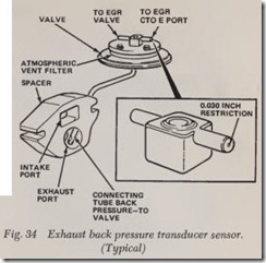
Some 1974, all 1975 California vehicles and all 1976 models are required to have an exhaust back pressure transducer sensor, Fig. 34. This device consists of a diaphragm valve, a spacer and a metal tube. The EGR valve is mounted to the sensor spacer and is modulated by the sensor.
The EGR system, when equipped with a back pressure sensor, obtains a vacuum signal at the carburetor spark port and not the EGR port. The vacuum signal passes through the EGR CTO (Coolant Temperature Override) switch (when coolant temperature exceeds ll5° or 160° F.) to the valve portion of the sensor where it is modu lated by exhaust back-pressure.
NOTE: The inlet nipple of the exhaust back-pres sure sensor has a .030 inch restriction. The vacuum line from the EGR CTO must be connected to this nipple.
When exhaust back-pressure is relatively high, as during acceleration and some cruising condi tions, exhaust back-pressure traveling through the metal tube overcomes spring tension on the dia phragm within the back-pressure sensor valve, and closes the valve atmospheric vent.
With the back-pressure sensor valve no longer vented to atmosphere, the vacuum signal now passes through the back-pressure sensor valve, and the EGR valve. When vacuum signals the EGR valve, exhaust gas recirculation commences.
When exhaust back-pressure is too low to over come diaphragm spring tension, the vacuum signal is vented to atmosphere and does not pass through to the EGR valve. With no vacuum signal applied to the EGR valve, exhaust gas does not recirculate.
All six cylinder and some VS-304, 360 engines incorporate a steel restrictor plate under the ex haust back-pressure sensor. The restrictor plate limits the rate of EGR flow, thereby improving driveability. Note that gaskets are used on both sides of the plate.
The back-pressure sensor is not serviceable and must be replaced if defective.
EGR Back-Pressure Valve & Sensor Unit
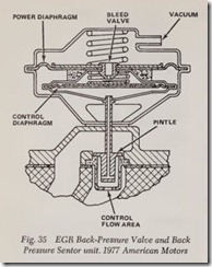
On 1977 vehicles, the exhaust back pressure sen sor is an integral part of the EGR valve Fig. 35 thereby combining the functions of the EGR valve and exhaust back pressure sensor into one unit. Calibration of this unit is accomplished by using different diaphragm spring loads and flow control orifices .
Exhaust gas recirculation is controlled by the movable pintle. In the closed position, spring pres sure holds the pintle against its seat, confining the exhaust gases in the exhaust manifold. While the vacuum bleed valve in the power diaphragm is open, carburetor vacuum cannot pull the pintle off its seat. When the exhaust back pressure con ducted through the hollow pintle is enough to overcome control spring pressure, full vacuum is applied to the power diaphragm and the pintle moves to start EGR. When back pressure drops sufficiently, the control diaphragm moves away from the bleed valve to stop EGR.
THERMOSTATIC CONTROLLED
AIR CLEANER, TAC & AUTO-THERM
AIR CLEANER SYSTEMS
American Motors
Mechanically Controlled
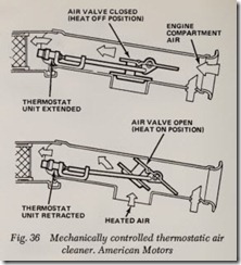
This system consists of a heat shroud placed over the exhaust manifold, a hot air hose, and an air duct and valve assembly, Fig. 36.
The air duct and valve assembly regulates the temperature of air entering the air cleaner by se lecting either air from the engine compartment, or heated air from the shrouded exhaust manifold.
During engine warmup when the air tempera ture entering the air duct is less than the calibrated temperature, the thermostat is in the retracted position and the air valve is held in the open posi tion (heat on) by the spring, thus allowing hot air How from the shrouded exhaust manifold.
As air temperature passing around the thermostat unit rises, the thermostat starts to open, pulling the air valve down and allowing cooler air from the engine compartment to enter the air cleaner. When the incoming air reaches the calibrated op erating temperature, the air valve is in the closed position (heat off) so that only engine compart ment air enters the air cleaner.
Vacuum Controlled
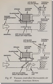
This system consists of a heat shroud, a hot air hose, a thermal sensor and a vacuum motor and air valve assembly, Fig. 37.
The thermal sensor incorporates a bleed valve which regulates the amount of vacuum applied to the vacuum motor which controls the air valve position to supply either heated air from the ex haust manifold or air from the engine compart ment.
During engine warmup when underhood air temperatures are low, the air bleed valve is closed allowing sufficient vacuum to be applied to the vacuum motor, holding air valve in the open position.
As the air temperature entering the air cleaner reaches the calibrated temperature, the bleed valve opens, decreasing the amount of vacuum applied to the vacuum motor. The diaphragm spring in the vacuum motor moves the air valve into the closed position (heat off), thus allowing only under hood air to enter the air cleaner.
During hard acceleration, manifold vacuum drops causing the valve to close regardless of tem perature to obtain maximum airflow through the air cleaner.
Ford Motor Co. Temperature Controlled
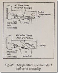
Carburetor air temperature is thermostatically
controlled by the air duct and valve assembly. Air from the engine compartment, or heated air from the shrouded exhaust manifold is supplied to the engine, Fig. 38.
During the engine warm-up period when the air temperature entering the air duct is less than 105° F., the thermostat is in the retracted position and the air valve is held in the closed position by the air valve spring, thus shutting off the air from the engine compartment. Air is then drawn from the shroud at the exhaust manifold.
As the temperature of the air passing the ther mostat unit rises, the thermostat starts to open and pulls the air valve down. This allows cooler air from the engine compartment to enter the air cleaner. When the temperature of the air reaches 130° F, the air valve is in the open position so that only engine compartment air is allowed to enter the air cleaner.
Vacuum Controlled
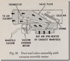
Some Ford systems incorporate a vacuum over ride motor, Fig. 39. This motor during cold acceleration periods provi des addition al air to car buretor. The decrease in intake manifold vacuum during acceleration causes the vacuum override motor to override the thermos tat control, opening the system to both engine compartmen t air and heated air from the exhaust manif old shroud.
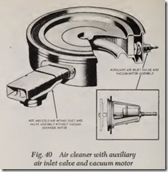
Yet another Ford application of same system uses a vacuum m otor, Fig. 40, installed on the perimeter of the air cleaner to take the place of the vacuum override motor. When the manifold vacuum is low, during heavy engine loading or high speed operation, a spring in the vacuum motor opens the motor valve plate into the air cleaner. This provides the maximum air supply for greater volumetric efficiency.
Thermostatically Controlled Vacu um Operated
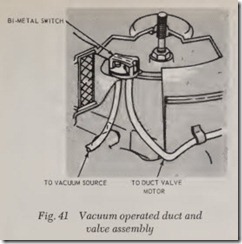
A vacuum operated duct valve with a thermo static bi-metal control, Fig. 41, is used on some installations. The valve in the duct assembly is in an open position when the engine is not operating. When the engine is operating at below normal operating temperature, manifold vacuum is routed through the bi-metal switch to the vacuum motor to close the duct valve allowing only heated air to enter the air cleaner . When the engine reaches normal operating temperature the bi-metal switch opens an air bleed which eliminates the vacuum, and the duct valve opens ·allowing only cold air to enter the air cleaner. During periods of acceler ation the duct valve will open regardless of tem perature due to the loss of manifold vacuum.
Cold Weather Modulator
This modulator, Fig. 42, located in the air clean er housing of some 1975-76 Ford vehicles, prevents the air cleaner door from opening to non-heated outside air at ambient temperatures below 55° F. At ambient temperatures above 55° F., the modu lator is inoperative. During acceleration at ambient temperatures below 55° F., the modulator located in-line betw een the bi-metal sensor and vacuum duct motor, will close off vacuum to the motor and hold the duct open.
Air Cleaner Temperature Switch
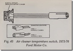
1975-76 vehicles with CTAV systems and those with Thermactor systems used with catalytic con verters, are equipped with a bi-metallic tempera ture switch mounted in the air cleaner housing. The two type switches used may be identified by the connector, Fig. 43. The first type has normally closed contacts, while the second type has nor mally open contacts. Refer to “Cold Engine Lock out” under “Air Pump Systems”, for operation of these switches.
All General Motors
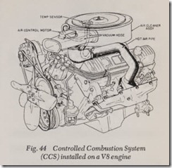
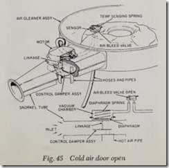
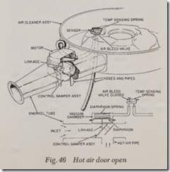
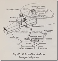
Figs. 44 thru 47. Carburetor air temperature is controlled by a pair of doors, located in the air cleaner snorkel, which channel either pre-heated or under hood air to the carburetor.
Preheated air is obtained by passing under hood air through ducts surrounding the exhaust manifold, causing it to pick up heat from the mani fold surface. The heated air is then drawn up through a pipe to the air cleaner snorkel.
Under hood air is picked up at the air cleaner snorkel in the conventional manner.The two air mixing doors work together so that as one opens, the other closes and vice versa. When under hood temperature is below approxi mately 90 deg. F., the cold air door closes, causing the hot air door to open. Hot air from the exhaust manifold stove is then drawn into the carburetor. As the under hood temperature increases, the cold air door begins to open until the temperature reaches approximately 115 to 130 deg. F., at which time the cold air door is fully open and the hot air door is fully closed.
The doors are controlled by a vacuum motor mounted on the air cleaner snorkel. This motor, in turn, is controlled by a sensor inside the air cleaner which regulates the amount of vacuum present in the vacuum motor according to air cleaner temperature. Whenever manifold vacuum drops below 5-8 inches, depending on the unit, the diaphragm sprin g in the motor will open the cold air door wide in order to provid e maximum airflow.
The vacuum motor and control door assembly in the left snorkel on outside air induction units does not have a sensor and is controlled only by manifold vacuum. This snorkel remains closed until full throttle is obtained. With manifold vac uum at 6-8 inches, the door will open, allowing maximum air flow.
![Fig. 42 Cold Weather Modulator System. 1975-77 Ford Motor Co._thumb[1] Fig. 42 Cold Weather Modulator System. 1975-77 Ford Motor Co._thumb[1]](http://machineryequipmentonline.com/electric-equipment/wp-content/uploads/2020/06/Fig.-42-Cold-Weather-Modulator-System.-1975-77-Ford-Motor-Co._thumb1_thumb.jpg)
