Transistor substitution
Numerous guides have been prepared by manufacturers to provide cross-references for transistor substitution, with many being posted on the Internet. Most substitutions can be made with confidence.
If the transistor is unlisted or the number of the transistor is missing, the following procedure can be used to make an accurate replacement selection:
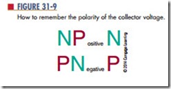
1. NPN or PNP? The first source of information is the symbol on the schematic diagram. If a schematic is not available, the polarity of the voltage source between the emitter and collector must be determined. If the collector voltage is positive with respect to the emitter voltage, then it is an NPN device. If the collector voltage is negative with respect to the emitter voltage, then it is a PNP device. An easy way to remember the polarity of the collector voltage for each type of transistor is shown in Figure 31-9.
2. Germanium or silicon? Measure the voltage from the emitter to the base. If the voltage is approximately 0.3 V, the transistor is germanium. If the voltage is approximately 0.7 V, the transistor is silicon.
3. Operating frequency range? Identify the type of circuit and determine whether it is working in the audio range, the kilohertz range, or the megahertz range.
4. Operating voltage? Voltages from collector to emitter, collector to base, and emitter to base should be noted either from the schematic diagram or by actual voltage measurement. The transistor selected for replacement should have voltage ratings that are at least three to four times the actual operating voltage. This helps to protect against voltage spikes, transients, and surges that are inherent in most circuits.
5. Collector current requirements? The easiest way to determine the actual current is to measure the
current in the collector circuit with an ammeter. This measurement should be taken under maximum power conditions. Again, a safety factor of three to four times the measured current should be allowed.
6. Maximum power dissipation? Use maximum voltage and collector current requirements to determine maximum power requirements (P 5 IE). The transistor is a major factor in determining power dissipation in the following types of circuits:
● Input stages, AF, or RF (50 to 200 mW)
● IF stages and driver stages (200 mW to 1 W)
● High-power output stages (1 W and higher)
7. Current gain? The common emitter small signal DC current gain referred to as hfe or Beta (ß) should be considered. Here are some typical gain categories:
● RF mixers, IF and AF (80 to 150)
● RF and AF drivers (25 to 80)
● RF and AF output (4 to 40)
● High-gain preamps and sync separators (150 to 500)
8. Case style? Frequently, there is no difference between the case styles of original parts and recommended replacements. Case types and sizes need only be considered where an exact mechanical fit is required. Silicon grease should always be used with power devices, to promote heat transfer.
9. Lead configuration? This is not a prime consideration for replacement transistors, although it may be desirable for ease of insertion and appearance.
Questions
1. Where can suggestions for transistor replacements be found?
2. Why does it matter whether a transistor is germanium or silicon?
3. Why are the operating frequency, voltage, current, and power ratings important when replacing a transistor?
4. What does the transistor’s Beta refer to?
Are the transistor’s case and lead configuration important when substituting a transistor?
