Applications of Capacitive Circuits
Capacitors can be used alone or combined with resistors to form RC (resistor-capacitor) networks. RC networks are used for filtering, decoupling, DC blocking, or coupling phase-shift circuits.
A filter is a circuit that discriminates among frequencies, attenuating (weakening) some while allowing others to pass. It works by establishing a cutoff point between frequencies that are passed and frequencies that are attenuated. The two most common types of filters are low-pass filters and high-pass filters. A low-pass filter allows low frequencies to pass with little opposition while attenuating the high frequencies. A high-pass filter permits frequencies above the cutoff point to pass while attenuating frequencies below the cutoff point.
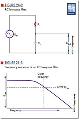
A low-pass filter (Figure 24-2) consists of a capaci- tor and a resistor in series. The input voltage is applied across both capacitor and resistor. The output is taken
from across the capacitor. At low frequencies, the capacitive reactance is higher than the resistance, so most of the voltage is dropped across the capacitor. Therefore, most of the voltage appears across the output. As the input frequency increases, the capacitive reactance decreases, and less voltage is dropped across the capacitor. There- fore, more voltage is dropped across the resistor, with a decrease in the output voltage. The cutoff is gradual. Frequencies above the cutoff point pass with a gradual attenuation in the output voltage. Figure 24-3 shows a frequency response curve for an RC low-pass filter.
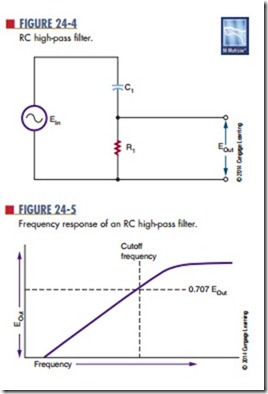
A high-pass filter also consists of a resistor and capacitor in series (Figure 24-4). However, the output is taken across the resistor. At high frequencies, the capacitive reactance is low, and most of the voltage is dropped across the resistor. As the frequency decreases, the capacitive reactance increases, and more voltage is dropped across the capacitor. This results in a decrease in the output voltage across the resistor. Again, the drop in output voltage is gradual. Figure 24-5 shows a frequency response curve for an RC high-pass filter.
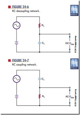
Most electronic circuits include both AC and DC voltages. This results in an AC signal superimposed on a DC signal. If the DC signal is used to operate equipment, it is advantageous to remove the AC signals. An RC low-pass filter can be used for this purpose. A decoupling network (Figure 24-6) allows the DC signal to pass while attenuating or eliminating the AC signal. The AC signal may be in the form of os- cillations, noises, or transient spikes. By adjusting the cutoff frequency, most of the AC signal can be filtered out, leaving only the DC voltage across the capacitor.
In another application, it may be desirable to pass the AC signal while blocking the DC voltage. This type of circuit is called a coupling network (Figure 24-7). An RC high-pass filter can be used. Initially the capacitor charges to the DC voltage level. Once the capacitor is charged, no more DC current can flow in the circuit. The AC source causes the capacitor to charge and discharge at the AC rate, creating current flow through the resistor. The component values are chosen so that the AC signal is passed with a minimum of attenuation.
At times, it is necessary to shift the phase of the AC output signal with respect to the input signal. RC networks can be used for phase shifting applications. The rC phase-shift networks are used only where small amounts, less than 60°, of phase shift are desired.
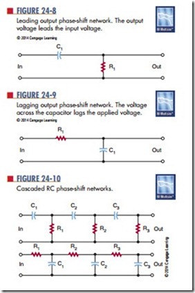
Figure 24-8 shows an RC phase-shift network with the input applied across the resistor-capacitor combination and the output taken across the resistor. In the circuit, the current leads the voltage because of the capacitor. The voltage across the resistor is in phase with the resistor, which results in the output voltage leading the input voltage.
In Figure 24-9, the output is taken across the capacitor. The current in the circuit leads the applied voltage. However, the voltage across the capacitor lags behind the applied voltage.
To achieve greater phase shifts, several RC net- works may be cascaded (connected) together (Figure 24-10). Cascaded networks reduce the output
voltage, however. An amplifier is needed to raise the output voltage to the proper operating level.
Phase-shift networks are valid for only one frequency, because the capacitive reactance varies with changes in frequency. Changing the reactance results in a different phase shift.
Questions
1. What are three uses of resistor-capacitor networks in electronic circuits?
2. Draw a diagram of a low-pass filter, and describe how it works.
3. Draw a diagram of a high-pass filter, and describe how it works.
4. What is the purpose of a decoupling network?
5. What do RC phase shift networks do?


