Wheatstone Bridge
A Wheatstone bridge is a measuring instrument that was invented by Samuel Hunter Christie in 1833. In 1843, a talented and versatile scientist named Sir Charles Wheatstone improved on the original design of the Wheatstone bridge. He did not claim to have invented the circuit named after him, but he was the first to use the circuit effectively for making resistance measurements.
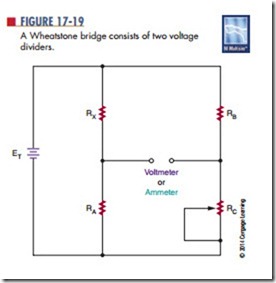
The Wheatstone bridge consists essentially of two voltage dividers (Figure 17-19). It is used to measure an unknown electrical resistance by balancing one leg that includes the unknown component against another leg of known components, with one being variable.
In the circuit, RX is the unknown resistor value. RC is a potentiometer and is adjusted until the voltage from the second voltage divider is equal to voltage from the voltage divider containing RX. When the voltage values are equal, the bridge balanced. The balance point can be detected by connecting either a voltmeter or an ammeter across the output terminals. Both meters will give a zero reading when a balance is achieved.
17–5 QueStionS
In a balanced circuit, the ratio RX/RA is equal to the ratio RB/RC.
1. Who invented the Wheatstone bridge?
2. What is the Wheatstone bridge circuit constructed of?
3. When the meter reads 0, what does this mean?
4. What is the value of rX when rA and rB are
RA
[
RX 5
RC
10 kΩ each and rC is 96,432 Ω?
5. What are other quantities that can be mea-
sured using the Wheatstone bridge concept?
6. What applications are used today for the Wheatstone bridge?
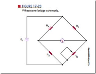
In other words, if the values of RA, RB, and RC are known, it is easy to calculate RX. RC would have to be measured with a meter to determine its value after adjusting for a zero reading. In an actual Wheatstone bridge test instrument, RA and RB are fixed, RC is adjusted, and RX can be easily read off a sliding scale connected to RC. The circuit for a Wheatstone bridge as designed by Wheatstone is shown in Figure 17-20. This is how the circuit is drawn for applications using it.
Variations on the Wheatstone bridge can be used to measure capacitance, inductance, and impedance.
Wheatstone bridge circuits are rarely used today to measure resistance values. They are now used for de-signing sensing circuits such as strain gauges for transforming a strain applied to a proportional change of resistance, widely used in industry; variometers to detect changes in air pressure for alerting glider pi- lots to updrafts or thermals so height can be gained allowing for longer flights; and explosimeters for sampling the amount of combustible gases in a space.


