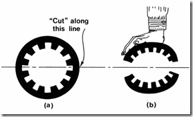
In principle, for each rotary IM there is a linear motion counter-part. The imaginary process of cutting and unrolling the rotary machine to obtain the linear induction motor (LIM) is by now classic (Figure 2.14). [1]
The primary may now be shorter or larger than the secondary. The shorter component will be the mover. In Figure 2.14 the primary is the mover. The primary may be double sided (Figure 2.14d) or single sided (Figure 2.14 c, e).
The secondary material is copper or aluminum for the double-sided LIM and it may be aluminum (copper) on solid iron for the single-sided LIM. Alternatively, a ladder conductor secondary placed in the slots of a laminated core may be used, as for cage rotor rotary IMs (Figure 2.14c). This latter case istypical for short travel (up to a few meters) low speed (below 3 m/s) applications.
Figure 2.14 Cutting and unrolling process to obtain a LIM
Finally, the secondary solid material may be replaced by a conducting fluid (liquid metal), when a double sided linear induction pump is obtained. [2]
All configurations on Figure 2.14 may be dubbed as flat ones. The primary winding produces an airgap field with a strong traveling component at the linear speed us.
The number of pole pairs does not influence the ideal no-load linear speed us. Incidentally, the peripheral ideal no-load speed in rotary IMs has the same formula (2.5) where τ is the pole pitch (the spatial semiperiod of the traveling field).
In contrast to rotary IMs, the LIM has an open magnetic structure along the direction of motion. Additional phenomena called longitudinal effects occur due to this. They tend to increase with speed, deteriorating the thrust, efficiency, and power factor performance. Also, above 3 to 5 m/s speed, the airgap has to be large (due to mechanical clearance constraints): in general, 3 to 12 mm. This
leads to high magnetization currents and thus a lower power factor than in rotary IMs.
However, the LIM produces electromagnetic thrust directly and thus eliminates any mechanical transmission in linear motion applications
(transportation).
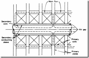
Apart from flat LIM, tubular LIMs may be obtained by rerolling the flat LIM around the direction of motion (Figure 2.15).
Figure 2.15 The tubular linear induction motor
The coils of primary winding are now of circular shape. The rotor may be an aluminum cylinder on solid iron. Alternatively, a secondary cage may be built. In this case the cage is made of ring shape-bars. Transverse laminations of disc shape may be used to make the magnetic circuit easy to manufacture, but care must be excersized to reduce the core losses in the primary. The blessing of circularity renders this LIM more compact and proper for short travels (1 m or less).
In general, LIMs are characterized by a continuous thrust density (N/cm2 of primary) of up to 2 (2.5) N/cm2 without forced cooling. The large values correspond to larger LIMs. The current LIM use for a few urban transportation systems in North America, Middle East, and East Asia has proved that they are rugged and almost maintenance free. More on LIMs in Chapter 20.
2.3. OPERATION PRINCIPLES OF IMs
The operation principles are basically related to torque (for rotary IMs) and, respectively, thrust (for LIMs) production. In other words, it is about forces in traveling electromagnetic fields. Or even simpler, why the IM spins and the LIM moves linearly. Basically the torque (force) production in IMs and LIMs may be approached via
• Forces on conductors in a travelling field
• The Maxwell stress tensor [3]
• The energy (coenergy) derivative
• Variational principles (Lagrange equations) [4]
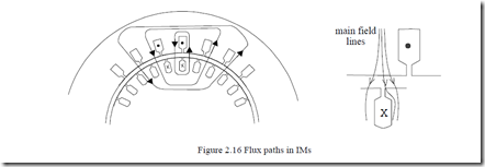
The electromagnetic traveling field produced by the stator currents exists in the airgap and crosses the rotor teeth to embrace the rotor winding (rotor cage)−Figure 2.16. Only a small fraction of it radially traverses the top of the rotor slot which contains conductor material.
It is thus evident that, with rotor and stator conductors in slots, there are no main forces experienced by the conductors themselves. Therefore, the method of forces experienced by conductors in fields does not apply directly to rotary IMs with conductors in slots.
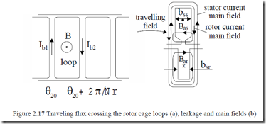
The current occurs in the rotor cage (in slots) because the magnetic traveling flux produced by the stator in any rotor cage loop varies in time even at zero speed (Figure 2.17). If the cage rotor rotates at speed n (in rps), the stator-produced traveling flux density in the airgap (2.2) moves with respect to the rotor with the relative speed nsr.
nsr = pf11 −n = S⋅pf11 (2.6)
In rotor coordinates, (2.2) may be written as.
B(θr,t)= Bm cos p( 1 2θ − ωS 1t) (2.7)
Consequently, with the cage bars in slots, according to electromagnetic induction law, a voltage is induced in loop 1 of the rotor cage and thus a current occurs in it such that its reaction flux opposes the initial flux.
The current which occurs in the rotor cage, at rotor slip frequency Sf1 (see (2.7)), produces a reaction field which crosses the airgap. This is the main reaction field. Thus the resultant airgap field is the product of both stator and rotor currents. As the two currents tend to be more than 2π/3 when shifted, the resultant (magnetization) current is reasonably low; in fact, it is 25 to 60% of the rated current depending on the machine airgap g to pole pitch τ ratio. The higher the ratio τ/g, the smaller the magnetization current in p.u.
The stator and rotor currents also produce leakage flux paths crossing the slots: Bas and Bar.
According to the Maxwell stress tensor theory, at the surface border between mediums with different magnetic fields and permeabilities (µ0 in air, µ
≠µ0 in the core), the magnetic field produces forces. The interaction force component perpendicular to the rotor slot wall is. [3]
![]() Ftn = Bar(θr,t Bµ)0 tr (θr,t)ntooth (2.8)
Ftn = Bar(θr,t Bµ)0 tr (θr,t)ntooth (2.8)
The magnetic field has a radial (Btr) and a tangential (Bar) component only. Now, for the rotor slot, Bar(θr)−tangential flux density−is the slot leakage flux density.
Bar ( )θr = µ0Ibb(srθr,t) (2.9) The radial flux density that counts in the torque production is that produced by the stator currents, Btr(θr), in the rotor tooth.
Btr (θr,t)= B(θr,t)⋅btrb+srbsr (2.10)
In (2.10), btr is the mean rotor tooth width while B(θr,t) is the airgap flux density produced by the stator currents in the airgap.
When we add the specific Maxwell stress tensors [1] on the left and on the right side walls of the rotor slot we should note that the normal direction changes sign on the two surfaces. Thus the addition becomes a subtraction.
ftooth (N /m2 )= −Bar (θ + ∆θr ,t Bµ)0 tr (θ + ∆θr ,t) −Bar(θr,t Bµ)0 tr (θr,t) (2.11)
Essentially the slot leakage field Bar does not change with ∆θ−the radial angle that corresponds to a slot width.
ftooth (N /m2 )= − Barµ(θ0r,t)(Btr (θ + ∆θr ,t)−Btr (θr,t)) (2.12)
The approximate difference may be replaced by a differential when the number of slots is large. Also from (2.9):
ftooth (N /m2 )= − −Ibb(srθr,t)⋅∆∆θB(θslotr,t)⋅(btrb+srbsr )⋅∆θslot (2.13)
Therefore it is the change of stator produced field with θr, the traveling field existence, that produces the tangential force experienced by the walls of each slot. The total force for one slot may be obtained by multiplying the specific force in (2.13) by the rotor slot height and by the stack length.
It may be demonstrated that with a pure traveling field and rotor current traveling wave Ib(θr,t), the tangential forces on each slot pair of walls add up to produce a smooth torque. Not so if the field is not purely traveling.
Based on same rationale, an opposite direction tangential force on stator slot walls may be calculated. It is produced by the interaction of stator leakage field with rotor main reaction field. This is to be expected as action equals reaction according to Newton’s third law. So the tangential forces that produce the torque occur on the tooth radial walls. Despite this reality, the principle of IM is traditionally explained by forces on currents in a magnetic field.
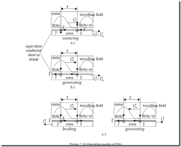
It may be demonstrated that, mathematically, it is correct to “move” the rotor currents from rotor slots, eliminate the slots and place them in an infinitely thin conductor sheet on the rotor surface to replace the actual slot-cage rotor configuration (Figure 2.18). This way the tangential force will be exerted directly on the “rotor” conductors. Let us use this concept to explain further the operation modes of IM.
Figure 2.18 Operation modes of IMs
→ →
a.) motoring: U U<s both in the same direction
→ →
b.) generating: U U>s ; both in the same direction
→ → → →
c.) braking: U opposite to Us ; either U or Us changes direction.
![]() The relative speed between rotor conductors and stator traveling field is U −Us , so the induced electrical field in the rotor conductors is.
The relative speed between rotor conductors and stator traveling field is U −Us , so the induced electrical field in the rotor conductors is.
![]() As the rotor cage is short-circuited, no external electric field is applied to it, so the current density in the rotor conductor J is
As the rotor cage is short-circuited, no external electric field is applied to it, so the current density in the rotor conductor J is
J = σAlE (2.15)
Finally, the force (per unit volume) exerted on the rotor conductor by the traveling field, ft, is
ft = J×B (2.16) Applying these fundamental equations for rotor speed U and field speed
→ →
![]() Us in the same direction we obtain the motoring mode for U <Us , and,
Us in the same direction we obtain the motoring mode for U <Us , and,
→ → respectively, the generating mode for U >Us , as shown on Figure 2.17a, b. In the motoring mode, the force on rotor conductors acts along the direction of motion while, in the generating mode, it acts against it. In the same time, the electromagnetic (airgap) power Pe is negative.
![]() Pe = f t ⋅Us >0 ; for motoring (ft> 0, U > 0)
Pe = f t ⋅Us >0 ; for motoring (ft> 0, U > 0)
Pe = f t ⋅Us <0; for generating (ft< 0, U > 0) (2.17)
![]()
![]()
![]()
![]() This simply means that in the generating mode the active power travels from rotor to stator to be sent back to the grid after losses are covered. In the braking mode (U < 0 and Us> 0 or U > 0 and Us< 0), as seen in Figure 2.18c, the torque acts against motion again but the electromagnetic power Pe remains positive ( Us >0 and f t >0 or Us <0 and f t <0 ). Consequently, active power is drawn from the power source. It is also drawn from the shaft. The summation of the two is converted into induction machine losses.
This simply means that in the generating mode the active power travels from rotor to stator to be sent back to the grid after losses are covered. In the braking mode (U < 0 and Us> 0 or U > 0 and Us< 0), as seen in Figure 2.18c, the torque acts against motion again but the electromagnetic power Pe remains positive ( Us >0 and f t >0 or Us <0 and f t <0 ). Consequently, active power is drawn from the power source. It is also drawn from the shaft. The summation of the two is converted into induction machine losses.
The braking mode is thus energy intensive and should be used only at low frequencies and speeds (low Us and U), in variable speed drives, to “lock” the variable speed drive at standstill under load.
The linear induction motor operation principles and operation modes are quite similar to those presented for rotary induction machines.
