An electric motor is a type of electromechanical energy conversion device that converts electric energy into mechanical energy. The principle of torque production in a motor can be understood by analyzing its energy conversion process. Electromechanical energy conversion devices normally use the magnetic field as an intermediate in their energy conversion processes. Thus an electromechanical energy conversion device is composed of three different parts: the electric system, magnetic system, and mechanical system as shown in Fig. 1.7
Now, we will examine the mechanism of torque production of a motor by looking at how the force (or torque) is being produced inside the electromechanical energy conversion device
To evaluate the force (or torque) produced inside the energy conversion devices, we will apply the law of conservation of energy: “within an isolated system, energy can be converted from one kind to another or transferred from one place to another, but it can neither be created nor destroyed.” Therefore the total amount of energy is constant. Fig. 1.8 shows an application of the law of conservation of energy when the electromechanical energy conversion device is acting as a motor. Suppose that electric energy dWe is supplied to the energy conversion device during the differential time interval dt. The supplied electric energy dWe is converted to field energy dWf in the magnetic system, and to mechanical energy dWe in the mechanical system.
In addition a small amount of electric energy dWe is converted into losses in each of the three parts: copper losses in an electric system, core losses such as hysteresis and eddy current losses in a magnetic system, and mechanical losses such as friction and windage losses. Since these losses may be dissipated in the form of heat or noise, we can leave out these losses in the process of evaluating the force or torque production in the energy conversion process. Therefore the energy conversion equation in Fig. 1.8 may be written as
1.2.1 MAGNETIC ENERGY
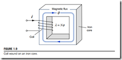
In electric machines, including a motor, the magnetic flux is normally produced by the coil wound on an iron core as shown in Fig. 1.9. Because ferromagnetic materials such as an iron core have high permeability, much greater magnetic flux can be developed in the iron core for a given current than when the magnetic flux is developed in the air. Now, we will take a look at magnetic energy Wf stored in the magnetic system, where magnetic flux φ is developed in the iron core as shown in Fig. 1.9
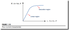
First, we need to know the relationship between the magnetic flux φ produced in the core and the coil current i in this magnetic system. Fig. 1.10 demonstrates this relationship, which is the B H characteristic called magnetization curve. In the beginning of the curve, the magnetic flux φ increases rapidly in proportion to the increase in the coil current i until it reaches a certain value. The region where the magnetic flux is linearly related to the applied current like this is called the linear region or unsaturated region.
However, above that certain value, further increases in the current produce relatively smaller increases in the magnetic flux. Eventually an increase in the current will produce almost no change at all in the magnetic flux. The region where the curve flattens out is called the saturation region, and the iron core is said to be saturated. When the saturation occurs, any further increase in the current will have little or no effect on the increase of the flux. In electric machines, the magnetic flux is designed to be produced as much as possible because their torque is directly proportional to the magnetic flux. Thus most electric machines normally operate near the knee of the magnetization curve, which is the transition range between the two regions.
Electric machines produce the magnetic flux by using coils, which normally consist of many turns. Thus, instead of the magnetic flux φ, the concept of flux linkage λ as a product of the number of turns N and the magnetic flux φ linking each turn is introduced. The flux linkage of N turn coil can be given by
λ 5 Nφ ðWb-turnsÞ (1.2)
The flux linkage λ can also be related to the coil current i by the definition of inductance L through the following relation.
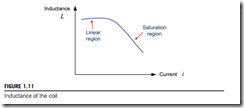
A larger inductance value of the magnetic system implies that the same current can produce a larger flux linkage. Eq. (1.3) shows that the slope of the curve in Fig. 1.10 is the inductance of this magnetic system as shown in Fig. 1.11
The inductance is large and relatively constant in the unsaturated region but gradually drops to a very low value as the core becomes heavily saturated.
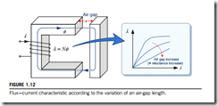
Now, we will take a look at magnetic energy Wf stored in the magnetic system, where magnetic flux φ is developed in the iron core as shown in Fig. 1.12. The λ 2 i characteristic of the magnetic system varies with the air gap length x. Thus the inductance LðxÞ of the coil is expressed as a function of the air gap length x.As the air gap length x increases, the slope of the λ 2 i curve becomes smaller and results in smaller inductance as shown in Fig. 1.12
The inductance L of the magnetic system is inversely related to its reluctance ℜ, which is defined as the ratio of magnetomotive force (mmf) Fð 5 NiÞ to magnetic flux φ, as in the following relation.
Now, assume that the source voltage v is applied to the terminals of the N turn coil on the iron core during dt as shown in Fig. 1.13. Then, the current i will flow in that coil. The resulting mmf Fð 5 NiÞ will produce a magnetic flux φ in the core and establish flux linkage λð 5 NφÞ in the coil. Now, we will discuss the energy stored in the magnetic system


