VIDEORECORDER SIGNAL PROCESSING
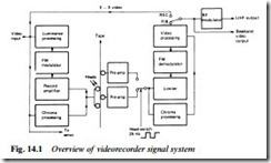
Many processes have to be carried out on the CVBS signal in order to get it through the head/tape system in both directions while maintaining reasonable fidelity. The complete record/playback video signal system is outlined in Fig. 14.1, where it can be seen that luminance and chrominance signals are separately dealt with throughout the recording and replay circuits, only coming together at a late stage in the playback processing circuit.
RECORD LUMINANCE SYSTEM
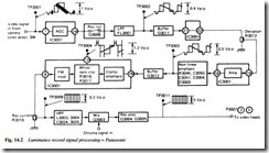
Fig. 14.2 gives a simplified block diagram of a typical luminance recording process. It is based on a single IC, here designated IC3001 – the numbers in rings denote chip pin numbers, and significant waveforms are annotated. The CVBS signal enters the IC on pin 1 where it passes through an a.g.c. stage. It operates on sync pulse amplitude (always 30% of a standard 1 V p-p video signal) to maintain a constant amplitude of output signal without affecting black level or mean level of the video signal.
Emerging from IC pin 24 and passing through the transistor ‘record switch’ Q3009, the CVBS signal enters low-pass filter FL 3001, whose response rolls off sharply at about 4 MHz to strip away all chroma
signal – at TP 3002 appears a pure luminance signal. It is buffered in emitter-follower Q3011 and attenuated in the adjustable deviation preset R3012. It is the amplitude of the signal which determines the upper limit of f.m. modulator deviation, and R3012 is adjusted for 4.8 MHz f.m. output during peak-white.
To reduce noise in f.m. systems the high-frequency components of the modulating signal are customarily boosted, a process called pre- emphasis. For optimum noise performance non-linear emphasis is used, in which small-amplitude h.f. components are given a greater boost than large-amplitude ones – the selection here is made by a diode level-detection circuit D3004, D3005. After buffering, the pre- emphasised luminance signal re-enters the chip on pin 16. Here the sync tip is clamped once per line to a fixed voltage which defines the f.m. modulator frequency for sync tip: in this VHS machine it is 3.8 MHz. The associated emphasis stage has a rising frequency response, offering some 15 dB gain at luminance frequencies around 2 MHz, compared with 6 dB gain at 250 kHz.
The effect of pre-emphasis is to introduce overshoots at transitions in the luminance signal as the waveform for TP3004 shows. If these spikes extend too far above peak white or below sync tip levels there is a risk that the modulator will over-deviate to generate excessive side- band energy – it is prevented by amplitude limiters controlled by white and dark clip control presets R3016/R3017. Finally the luminance signal is applied to the f.m. modulator, a form of voltage-controlled oscillator. Again this is incorporated in IC3001, and takes the form of an astable multivibrator; its charging capacitors have the luminance waveform as an aiming voltage so that the output squarewave frequency is governed by the level of the processed luminance waveform. The f.m. signal emerges at IC3001 pin 9 and is developed across record-current preset R3019: its slider taps off a suitable proportion (about 200 mV p-p) to set correct luminance writing current.
Since the colour-under signal will occupy the 0–1 MHz spectrum, it is important to remove any harmonics, beat frequencies and vestiges of sidebands in this region that may be present in the output of the modulator; the LC high-pass filter L3003 etc. traps out such l.f. components to prevent the risk of beat patterns during playback. The filtered f.m. signal is now added to the chroma record signal in Q3003 for onward passage to the recording amplifier, a two-transistor class B push-pull power amplifier section which drives around 5 V p-p into the rotating transformer and hence the video heads themselves. The frequency response of this amplifier is tailored to compensate for head response shape and the gain/frequency characteristic of the head/tape interface. Although the arrangement shown in Fig. 14.2 and other diagrams here has now been superseded it remains a better model for explanation of the principles than the highly integrated system to be described later in this chapter.
So far as recording f.m. and chroma frequencies are concerned, Fig. 14.3 gives the characteristics of the two main domestic formats.
High-band video recording
Both VHS and Video 8 formats have high-band variants known respectively as S-VHS and Hi-8. They differ from the standard systems described above in one main respect: the deviation of the carrier. Using high-grade small-particle tape and extra-narrow video head gaps, the usable frequency response is pushed up to achieve a picture definition of more than 400 lines. For S-VHS the carrier deviation is 5.4 MHz (sync tip) to 7 MHz (peak white), and for Hi-8, 5.7 MHz (sync tip) to 7.7 MHz (peak white). In the latter case the recorded wavelength is around 0.4 micron.
The second feature of high-band domestic videorecorders is provision for keeping the luminance and chrominance components of the video signal separate throughout the machine, and thus avoiding the cross-colour penalty of band-shared colour-encoding systems. It is not relevant to terrestrial and f.m. satellite broadcasts, but gives very good results from MAC and digital broadcasts and high-band camcorders. In these systems the standard connector is the S-terminal, whose plug wiring details are given in Fig. 24.2(f).

