PCM audio
All newly developed hi-fi audio systems use digital encoding: examples are compact disc, the NICAM TV stereo plan, DAB radio broadcasting and digital TV. Although digital transmission and recording requires more bandwidth than other systems it has the advantages that the two-state sig- nal is more robust than its analogue counterpart, and (so long as the quan- tising rate is high) is capable of superb S/N ratio and wider dynamic range.
The Video-8 format has provision for stereo PCM in addition to the monophonic AFM sound facility described above. The most expensive Video-8 camcorders and homebase VCRs are fitted up for PCM operation. It is impractical to give full details of the system in this book, and what fol- lows is a basic outline of the technique used.
Figure 21.39 shows the functional blocks in the PCM sound processing. Initially, the audio signal for record is amplitude compressed in a com- pander. Next follows a quantisation process in which it is sampled at 2 fh, (31.25 kHz) to 10-bit resolution. Since the tape system here cannot cope with 10-bit data, a conversion is carried out to 8-bit: the process is a non- linear one, in which low-level signals are in effect given 10-bit (1024-level)
descriptions, falling in three stages – as signal level increases—to 7-bit data (128-level) for the largest signal excursions. This has the effect (during playback) of concealing quantising noise in the loudest sound peaks, where they go virtually unnoticed; indeed the overall S/N ratio is subjectively equivalent to 90 dB.
Unless their transmission/recording media are very secure, digital data systems need error-correcting artifices to repair or conceal corruption of the data by noise and distortion. About 38.5% redundancy is imparted to the PCM audio data by the addition to it of further data in the form of a cyclic redundancy check code (CRCC) – used during playback for error detection and correction. The data rate is high, and the effect of a tape dropout would ordinarily blow a hole in the information stream; to pre- vent this the data is ‘scattered’ on tape according to a cross-interleave code (CIC), part of the Video-8 format. The effect of a tape dropout thus becomes distributed during replay, and the ‘frayed edges’ can be repaired by use of the CRCC and an additional parity check system.
The 8-bit data words are now temporarily stored in a pair of 16K RAM memories. Writing to memory is performed in real time. Readout from memory is much faster: all the data (which contains information on both stereo channels) is clocked out in less than 3 ms at 20 ms intervals. The effect of this 7:1 time compression is to push up the data-rate to about 2 Mbps, but to confine the audio transmission period to a small time-slot. As we shall see in a moment, a separate place is found on the video tape for this data-burst. Frequency shift keying (FSK) is used in which the bits are tone modulated at 2.9 MHz for 0 and 5.8 MHz for 1.
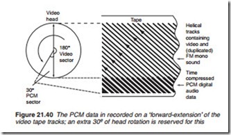
At this point, the PCM signal is ready to go onto tape. The switches on the right of Figure 21.39 change over once per field period, in synchronism with TV field rate and RAM readout. This feeds data to the video heads alter- nately, during a period when each is scanning a ‘forward extension’ of the helical vision track on tape – this is illustrated on the right of Figure 21.40. The conventional video tracks (which also contain AFM audio information, duplicating the PCM sound track) are recorded over 180° of the head track, but the head/tape angle is such that they occupy about 5.4 mm of the 8 mm tape width. The extra 30° or so of tape wrap shown on the right of Figure 21.40 is devoted to PCM recording: while one head is writing PCM data, the other (diametrically opposite on the drum) is recording the last lines of the TV picture at the top of the video tracks on the right of the diagram.
During playback, head switching ensures that PCM data read off the tape is routed to the audio section for the appropriate 30° scan/3 ms con- tinuing to the left in Figure 21.39, the data, still in time-compressed form, is read into the same pair of 16K memories as was used during record.
Memory readout takes place in ‘real time’, expanding the data to give continuous data at a lower bit-rate – that at which the memories were loaded during record. Readout sequence is governed by the cross inter- ference code (CIC) mentioned above in order to de-interleave the data, scattering and fragmenting errors in the process. In the memory control
chip is also carried out error correction by means of the CRCC and parity checks mentioned earlier. For dropouts too severe to be repaired by these means, interpolation provides a ‘patching’ system which in the face of sus- tained and continued corruption, devolves to a PCM mute action, switch- ing the audio output line back to the AFM sound track. If this is also corrupted, silence will ensue!
The 8-bit data now passes to the 10-bit conversion stage to make ready for D-A conversion. As is common in these designs, the record A-D converter is used for this, now switched to perform D-A operation. The analogue signal reconstituted at the D-A converter output is still in amplitude- compressed form, and is now expanded to full dynamic range in a logarith- mic compander.


