Full Layer III audio coder
In the Layer III audio coder (Figure 6.11), the output from the 32-phase filter is fed into a MDCT processor before going into the bit allocation block. Apart from compensating for the deficiencies of the poly-phase filter, the MDCT ensures critical sampling in which the number of coefficients is the same as the number of samples. A simple discrete frequency transform (DFT) will produce twice as many coefficients than samples because the 50% overlap of the windows results in the same samples falling into two adjacent windows. For this reason, sub-sampling is used to ensure that the number of samples reverts back to its non-overlapping level.
The FFT processor drives the psychoacoustic masking processor which drives the MDCT to determine the window size for each individual sub- band. The masking processor also produces a masking threshold for the quantising control unit. Following bit allocation, the bitstream is fed into a buffer to ensure a constant bit rate. When the buffer overflows, it sends a control signal to the quantising control unit to change the quantisation level to reduce the bit rate and vice versa. This process will also serve to remove pre-echo. During stationary sound material, the buffer contents are deliberately reduced by the quantiser. If a transient arrives, the increased number of coefficients may be handled by filling the buffer with- out increasing the quantisation level thus avoiding pre-echo. The audio bitstream as well as information on the quantisation level, scale factor and masking are formatted into an audio packet.
Advanced audio coding
AAC supports up to 48 audio channels incorporating mono, stereo and 5.1 audio. It was developed by MPEG to deliver the highest possible quality using newly developed compression tools. The driving force to develop AAC was the quest for an efficient coding method for surround sound like those being used in cinemas today. There have been algorithms for these signals in MPEG-2 for some time but further considerable reduction in bit rates was necessary.
MPEG-2 AAC was developed first and declared as an international standard in April 1997. It introduced temporal noise shaping (TNS) and inter-block prediction. MPEG-2 AAC was followed by MPEG-4 audio. MPEG-4 standardises natural audio coding at bit rates ranging from 2 kbps up to and above 64 kbps. When variable rate coding is allowed, coding at less than 2 kbps, such as an average bit rate of 1.2 kbps, is also supported. The presence of the MPEG-2 AAC standard within the MPEG-4 tool set provides for general compression of audio in the upper bit rate range. MPEG-4 AAC extends these tools by adding new techniques such as perceptual noise substitution (PNS), twin vector quantisation (TVQ) and long-term prediction (LTP).
MPEG-2 AAC
Like all perceptual coding schemes, a psychoacoustic model is used to simulate the ability of the human auditory system to perceive different fre- quencies. Tones at different frequencies with equal power are not per- ceived with equal power. The perceptual model is also used to model the masking effect of loud tones that mask quieter tones and quantisation noise around its frequency. The perceivable frequencies are divided into several frequency bands; this part of the signal spectrum is then analysed and a masking threshold is calculated.
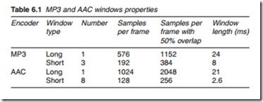
Although AAC has a similar structure to MP3, compatibility with other MPEG audio layers has been removed and AAC has no granule structure within its frames whereas MP3 might contain one or two granules per frame. Granules are used where, in order to reduce the number of bits used to describe a sample, a number of samples are quantised as a group. Furthermore, direct MDCT processing is performed over the PCM sample frames before the audio signal is divided into 32 sub-bands. The same tools (psychoacoustic filters, scale factors and Huffman coding) are applied to reduce the number of bits used for encoding. Another important differ- ence is that AAC has a better frequency resolution up to 1024 frequency lines compared with 576 for MP3. Similar to MP3 coding scheme, the two- window options are available before MDCT is performed in order to achieve a better time/frequency resolution. In the long window mode, MDCT is directly applied over 1024 PCM samples. In short windowing mode, an AAC frame is first divided into eight short windows each of which contains 128 PCM samples and MDCT is applied to each short window individually. Thus, in the short window mode, there are 128 frequency lines decreasing the spectral resolution by eight times whilst increasing the temporal resolution by the same factor. With a 48-kHz sampling rate, the length of the two windows are 1024/58 = 21.3 ms and 128/48 = 2.7 ms. With a 50% overlap, the windows sizes are 2 X 1024 = 2048 and 2 X 128 = 256 samples. Table 6.1 compares the 2-window options of MP3 and AAC.
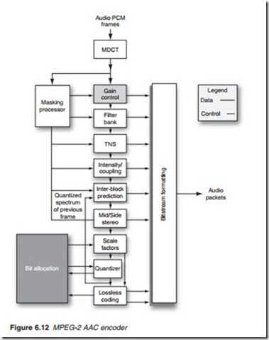
The basic structure of MPEG-2 AAC is illustrated in Figure 6.12. It intro- duces improvements to existing tools and few new tools. The crucial dif- ferences between MPEG-2 AAC and its predecessor MPEG audio Layer III are as follows:
Filter bank
A direct MDCT transformation is performed over the samples before dividing the audio signal in 32 sub-bands as in MP3 encoding. Similar to MP3 coding scheme, two 50% overlapping windows are used before MDCT is performed. At a sampling rate of 48 kHz, the window sizes cor- respond to a window of 21 and 2.6 ms.
Window shape
In AAC, the encoder can select the optimal shape for the windows between a Kaiser–Bessel-derived (KBD) window with improved far-off rejection of its filter response and a sine window with a wider main lobe.
Temporal noise shaping
This tool is an intra-block (within a block) compression technique which uses the values of previously filtered 20 or more coefficients to predict the current coefficient. The prediction is subtracted from the actual value and the prediction error or residual thus obtained is transmitted. At the decoder, an identical predictor is used to reverse the process.
Intensity/coupling
This is used where stereo or surround sound is transmitted at very low bit rate. It discards the spatial information related to the stereo and surround sound and transmits mono with amplitude codes to allow the signal to be panned out in the spatial domain at the receiving end.
Inter-block prediction
This technique exploits the fact that when sound is stationary or periodic with no transient, adjacent blocks exhibit great similarities in their quan- tised coefficients. A coefficient in a given block may then be predicted from the confidents at the same location in two previous blocks. As before, the prediction is subtracted from the actual value and a residual error is obtained and transmitted. The predictor only operates on coefficients below 16 kHz. Prediction can only be used over a specified number of frames after which they have to be reset. Protracted use of prediction would result in errors and drift.
Mid-side stereo
This is a facility for converting multi-channel sound (stereo or surround) to the sum and difference format known as mid-side (M/S) format before quantising in cases where quality can be improved. In M/S stereo, the middle (sum of left and right) and side (difference of left and right) chan- nels are encoded. In surround sound, M/S format can be applied to the front and rear L/R pairs separately.
Quantisation
MPEG-2 AAC quantiser uses non-uniform steps resulting in finer control of quantisation resolution and improved coding gain.
Referring to Figure 6.12, the MPEG-2 AAC coder provides a good and consistent quality by dynamically switching between window sizes, intra- prediction (TNS) and inter-block prediction and the control of buffer occu- pancy to deal with peaks and transients.

