Software Development Systems and Assemblers

Software Development Systems and Assemblers

A software development system is a computer that enables the user to develop programs (soft­ware) with the assistance of other programs. The development process includes writing, modifying, testing, and debugging of the user programs. In the previous chapter, we dis­cussed how to write a simple assembly lan­guage program and translate its mnemonics into Hex code manually. In this chapter, we will de­velop assembly language programs with the help of four other programs: Editor, Assembler, Linker, and. Debugger. These programs enable the user to write programs in mnemonics, trans­late mnemonics into Hex and binary code, and debug the code. All the activities of the com­puter-hardware and software-are directed by another program, called the operating system.

. This chapter describes an IBM PC (Per­sonal Computer)-based software development system, its hardware, and related programs. It also describes its operating systems MS-DOS (Microsoft-Disk Operating System) and illus­trates the use of the assembler to write assem­bly language programs.

OBJECTIVES

· Describe the components of a software de­velopment system.

· List various types of floppy disks, and ex­plain how information is accessed from the disk.

· Define the operating system of a microcom­puter, and explain its function.

· Explain the functions of these programs: Editor, Assembler, Cross-assembler Linker (Loader), and Debugger.

· List the advantages of the assembler over manual assembly.

· List the assembler directives, and explain their functions.

· Write assembly language programs with ap­propriate directives.


ASSIGNMNTS on Introduction to Z80 Assembly Language Programming

ASSIGNMNTS

1. How is the accumulator different from the 8-bit general-purpose registers of the Z80 microprocessor?

2. Explain the function of the alternate registers.

3. What is a flag, and what is its function?

4. If the Z80 adds 87H and 79H, specify the contents of the accumulator and the status of the S, Z, and CY flags.

5. If the Z80 is an 8-bit microprocessor, why are the program counter and the stack pointer 16-bit registers?

6. If the Z80 has fetched the machine code located at the memory location 205FH, specify the contents of the program counter.

7. The index register IX holds the address 2058H• Specify the value of the dis­placement byte needed to make the effective address 2097H

8. The index register IY holds the address 2070H• Specify the value of the dis­placement byte in 2’s complement needed to make the effective address 2050H

9. List the six types of operations the Z80 performs.

10. Define opcode and operand, and specify the opcode and the operand in the instruction LD A, B.

11. Explain the instruction LD A, B. Specify the data source and destination.

12. If the instruction LD A, B is stored in memory location 2005H, what are the contents of the memory register?

13. Explain the instruction SUB H. List the operand implicit in the instruction.

14. Write mnemonics to load F8H into register C, and show the Hex codes with the memory address starting at 1800H

15. Write -logical steps to load the following three Hex numbers (2F, 47, and 7 A) into Z80 registers B, C, and D, respectively. Add the numbers, and save the / sum in register H. •

16. Translate the steps in the previous question into Z80 assembly language.

17. Redraw the flowchart in Figure 6.5 by interchanging the answers of the de­cision block. For example, the program sequence will be altered if the an­swer is "Yes." (Hint: The flowchart can have two End statements.)

Draw a flowchart to represent the following problem. Load two numbers into Z80 registers, and subtract the second number from the first number. If the result generates a borrow, display FFH at the output port of the system; otherwise, display the second number.


SUMMARY of Introduction to Z80 Assembly Language Programming

SUMMARY

This chapter introduced the Z80 programming model and provided an overview of the Z80 instruction set and the capability of the Z80 microprocessor. The im­portant concepts and topics discussed in this chapter can be summarized as follows:

· The Z80 microprocessor has six general-purpose 8-bit registers (B, C, D, E, H, and L) as a primary set. In addition, it includes the alternate set of these registers, all of which can be used to exchange information with the primary set. The registers Band C, D and E, and Hand L can be combined to perform some l6-bit operations.

· The ALU section of the Z80 includes accumulator A and the flag register to indicate six different data conditions. It also includes the alternate accumula­tor A’ and flag register F’, which can be used to exchange information with A and F, respectively.

· Four flags-Sign, Zero, Carry, and Parity/Overflow-can be used for decision making and tested in connection with Jump, Call, and Return instructions. Two flags-Half-Carry.and Add/Subtract-are used internally for BCD opera­tions and are unavailable for the programmer.

· The Z80 has four 16-bit registers-IX, IY, SP, and PC-used as memory pointers. Two index registers-IX and IY-can be used to point to memory location, and an address and the direction (backward or forward) can be specified with a displacement byte. The stack pointer (SP) is used to specify memory locations in a defined R/W memory segment called the stack. The program counter (PC) is used to sequence the program execution; it points to the next memory address from which the machine code is to be fetched.

· The Z80 includes two 8-bit special-purpose registers: Interrupt Vector (I) and Memory Refresh (R). The I register provides the high-order 8 bits of a 16-bit address to which the program is to be directed after an interrupt. The R regis­ter is a 7-bit counter and supplies an address for refreshing memory cells of a dynamic memory.

· The Z80 microprocessor operations are classified into six major groups: data copy (load), arithmetic, logic, bit manipulation, branch, and machine control.

· An instruction has two parts: opcode (operation to be performed) and oper­and (data to be operated on). The operand can be 8- or 16-bit data, an ad­dress, register, register pair, or it can be implicit.

· The method of specifying an operand is called the addressing mode.

· The instruction set is classified into four groups according to the word size: 1-, 2-, 3-, and 4-byte instructions.

· To write a simple assembly language program, the problem should be divided into small steps in terms of microprocessor operations, and these steps should be translated into Z80 mnemonics. Then, the Hex code is assembled by look­ing up the code in the instruction list; this is called either hand or manual assembly.

· To enter a program into the memory of a single-board microcomputer, Hex keys are used to enter the code, which is converted into binary code by the Key Monitor program of the system and stored in R/W memory. This binary code can then be read and executed by the microprocessor.


LIST OF SELECTED Z80 INSTRUCTIONS par 2

Most instructions are compatible with the 8080 instruction set, with a few exceptions. Notations used in the description of the instructions include

r = Z80 8-bit Register

rp = Register Pair

rs = Register Source

rx = Index Registers

rd = Register Destination

d= Displacement Byte

m = Memory

b = Bit

( ) = contents of l6-bit Memory Address or 8-bit I/O Address

1. Data Copy (Load) Instructions

Mnemonics

Bytes

Tasks

Data (8 bits and 16 bits) copy or load in registers

LD rd, rs

1

Copy data from source register rs into destina­tion register rd.

LD r, 8-bit

2

Load 8-bit into a register.

LD rp, 16-bit

3

Load 16-bit into register pair.

LD rx, 16-bit

4

Load 16-bit data into index register.

Data copy between registers and memory

LD A, (I6-bit)

3

Load accumulator from memory; the address is specified by 16-bit operand.

LD (I6-bit), A

3

Load memory from accumulator; the memory address is specified by 16-bit operand.

LD A, (rp)

1

Load accumulator from memory; the memory address is specified by the contents of register pair.

LD A, (rp)

1

Load memory from accumulator; the memory address is given by the contents of register pair.

LD (rp), A

1

Load register from memory; the address is specified by 16-bit contents in HL.

LD r, (HL)

1

Load memory from register; the address is specified by 16-bit contents in HL.

LD (HL), r

3

Copy memory contents into register r; the memory address is obtained by adding the contents of index register and the displace­ment byte d.

LD r,(rx + d)

3

Copy register contents into memory address shown by index register and the displacement (rx + d).

2. Arithmetic Instructions·

ADD A, r

1

Add register contents to accumulator.

ADD A, 8-bit

2

Add 8-bit data to accumulator.

ADD A, (HL)

1

Add memory contents to accumulator; the memory address is specified by the contents in HL.

SUB r

1

Subtract contents of register from accumulator.

SUB 8-bit

2

Subtract 8-bit data from accumulator.

SUB (HL)

1

Subtract memory contents from accumulator; the memory address is specified by the con­tents of HL.

INC r

1

Increment the contents of a register,

INC (HL)

1

Increment the contents of memory; the mem­ory address is specified by the contents of HL.

INC rp

1

Increment 16-bit contents in a register pair.

DEC r

1

Decrement the contents of a register.

DEC (HL)

1

Decrement the contents of memory; the mem­ory address is specified by the contents of HL.

DEC rp

1

Decrement 16-bit contents in a register pair.

3. Logic Instructions*

AND r

1

Logically AND the contents of a register with the accumulator.

AND 8-bit

2

Logically AND 8-bit data with accumulator.

AND (HL)

1

Logically AND the contents of memory with accumulator; the memory address is specified by the contents of HL.

CP r

1

Compare the contents of register with accumulator for Jess than, equal to, or greater than.

CP 8-bit

1

Compare 8-bit data with accumulator for less than, equal to, or greater than.

CP (HL)

1

Compare the contents of memory with accumulator for less than, equal to, or greater than; the memory address is specified by the con­tents of HL.

4. Bit Rotation

RLCA

1

Rotate each bit in the accumulator to the left position.

RLA

1

Rotate each bit in the accumulator including the carry C to the left position.

RRCA

1

Rotate each bit in the accumulator to the right position.

RRA

1

Rotate each bit in the accumulator including the carry C to the right position.

5. Branch Instructions

JP 16-bit

3

Change the program sequence (Jump) to mem­ory location specified by the l6-bit address.

JP Z, l6-bit

3

Change the program sequence (Jump) to mem­ory location specified by the l6-bit address if ‘the Zero (Z) flag is set.

JP NZ, l6-bit

3

Change the program sequence (Jump) to mem­ory location specified by the l6-bit address if the Zero (Z) flag is reset.

JP C, l6-bit

3

Change the program sequence (Jump) to mem­ory location specified by the l6-bit address if the Carry (C) flag is set.

JP NC, l6-bit

3

Change the program sequence (Jump) to mem­ory location specified by the l6-bit address if the Carry (C) flag is reset.

CALL l6-bit

3

Change the program sequence to the location of the subroutine.

RET

1

Return to the calling program after completing the subroutine sequence.

6. Machine Control Instructions

HALT

1

Suspend execution and wait.

NOP

1

Do not perform any operation.

7. Bit Rotation*

RLC r

2

Rotate each bit in register r to the left.

RL r

2

Rotate each bit in register r to the left, includ­ing Carry flag.

SLA r

2

Shift each bit in register r to the left.

8. Bit Manipulation

BIT b, r

2

Test bit b in register r, affecting the Z flag.

SET b, r

2

Set bit b in register r. ("b" represents bit posi­tion 0 to 7)

RES b, r

2

Reset bit b in register r.

9. Z80 Special (Conditional) Repetitive Instructions. The Z80 instruction set in cludes several instructions that are automatically repeated until a specified register becomes zero. These instructions are quite efficient in dealing with block transfer or counter applications. Some of these instructions are as follows:

CPDR

2

Compare memory contents specified by HL with the accumulator. Increment HL decre­ment BC, and repeat until BC =0, or A = contents of memory specified by HL.

DJNZ d

2

Decrement B, and if B ≠ 0, jump to memory address obtained by adding displacement byte to the program counter.

INDR

2

Read input port indicated by the C register, and store the byte in memory specified by HL register. Decrement B and HL, and continue until B = 0.

OTDR

2

Output the contents of memory specified by HL to port indicated by the C register. Decre­ment Band HL, and continue until B = 0.


LIST OF SELECTED Z80 INSTRUCTIONS

6.6 LIST OF SELECTED Z80 INSTRUCTIONS

The Z80 instruction set includes 158 instructions resulting in 694 machine codes. The following list is a representative sample of each group described in Section "’6.2. The purpose of the list is to show you the overall capability of the Z80 and some logical patterns in its instruction. You should not study these instructions in detail; instead, you should search for logical patterns. Once you recognize log­ical patterns, you will be able to recognize the function of an instruction even if you have not seen it before.

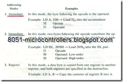
Z80 Addressing Modes

Explanation

Example

1. Immediate

The byte following the opcode is the operand. This mode is used to load 8-bit data into a register.

LD B, 97H

2. Immediate Extended :

The two bytes following the opcode are the operands. This mode is used to load I6-bit data or address into a register.

LDBC,8045H

3. Register

The operand register is included as a part of the opcode. This mode is used to copy data from one Z80 register into another register. Copy data from register A into B

LD B,A

4. Implied

This refers to orations in which the opcode implies one or more Z80 registers as containing the operands. For example, instructions for logic operations imply that the accumulator is one of the operands and that the result is stored in the accumulator. Logically AND register B with A

ANDB

5. Register Indirect

This mode is used to copy data between the MPU and memory; the 16-bit contents in a register pair are used as a memory pointer. Copy the contents of memory location 2060H into register B. Register HL contains the address 2060H.

LD B, (HL)

6. Extended

The two bytes following the opcode specify the jump location. Jump to location 2080H

JP 2080H

7. Relative

In this mode, the second byte specifies the displacement value in a signed 2’s complement for a jump location. Jump forward 20 locations from the address of the next instruction.

JR 14H

8. Indexed

In this mode, the byte following the opcode specifies a displacement value that is added to one of the index registers to form a memory pointer. The index register IX contains 2060H; increment the contents of memory location 2070H

INC (IX + 10H)

9. Bit

This mode is used for bit operation (manipulation). In this mode, instruction specifies a bit from a register or a-­memory location using one of the three addressing modes (register, register indirect, or indexed). Set bit D7 in register B.

SET 7, B

10. Page Zero

The instruction set includes eight restart (one-byte call) instructions on memory page zero. In this mode, the memory location can be specified by using the low-order. byte, and the high-order byte is assumed to be 00H.Call restart memory location 0028H.

RST 28H


ADDRESSING MODES

6. 5 ADDRESSING MODES

The addressing mode is a way of specifying an operand or pointing to a data location. The Z80 microprocessor has ten addressing modes, as shown in Table 6.1. The first three are explained here as illustrations, and the others will be explained in later chapters.

In Section 6.2.2, we listed various categories of data copy operations. Data can be loaded directly into registers (or memory), or they can be copied from registers and memory, including I/O ports. Here are the addressing modes of these data copy operations.

z80 Interfacing and programming-5_03

At this point, you are unfamiliar with the instruction types; therefore, you should avoid the details of the addressing modes given in Table 6.1. As we begin to use various instructions in following chapters, we will discuss the appropriate addressing modes. As you become more familiar with the instruction set, you will be able to choose an appropriate addressing mode for a given task.


FLOWCHARTING

6.4 FLOWCHARTING

A flowchart is a graphic representation of the logic and sequence of tasks to be performed. A flowchart should assist in clarifying one’s thinking process and communicate the programmer’s approach and logic in writing the program.

Flowcharting is an art; how much detail it should include requires a subjec­tive decision. At one level, the flowchart includes only the functions to be per­formed without any reference to a particular microprocessor; at another level, the functions of registers being used are specified in detail. However, it should not duplicate the instructions in the program in a graphic format; this would defeat the whole purpose of drawing the flowchart. It should simply represent a logical approach and sequence of steps in solving the problem.

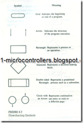
The six symbols commonly used in flowcharting are shown in Figure 6.7. We have already used three symbols in Figure 6.5. The fourth symbol, shown by the diamond shape, represents the decision-making block. It is used when data conditions need to be checked and the program sequence has to be altered. This symbol is i1lustrated in Figure 6.8. The fifth symbol, a double-sided rectangle, represents a predetermined process such as a subroutine (discussed in Chapter 10). The last symbol, a circle with an arrow, is used to show continuation of the flowchart to a different column or to a different page.

z80 Interfacing and programming-3_03

Example 6.2

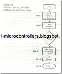
Draw a flowchart to represent the following problem. Load two Hex bytes into Z80 registers, and add the bytes. If the sum is larger than 8 bits, display O/H as the overload condition at port PORT7; otherwise, display the sum at the output port.

The problem can be divided into the following steps.

1. Load bytes into Z80 registers.

2. Add the bytes. .

3. Check the sum.

4. If the sum> FFH, display 01H at the output port.

5. If the sum < FFH, display the sum at the output port.

z80 Interfacing and programming-4_03

The steps listed in Example 6.2 and the sequence can be represented by the flowchart shown in Figure 6.8. The first two blocks can be easily understood. The third block, shown by the diamond shape, is a decision-making block. In this block the result is checked by examining the CY flag, and the program execution is altered accordingly. If the CY flag is set, the result is larger than FFH and the program execution goes to the next block. It loads 01 H and displays it at the output port. If the answer to the question in the decision block is "No," the sum is less than FF. The program sequence is then altered; it bypasses Block 4 and displays the sum at the output port.

An interesting question is: Can we interchange the answers "Yes" and "No" at the decision-making block? That is, can the program sequence be changed if CY is set? This is given as a problem at the end of the chapter: you may find that the resulting flowchart will have two end points.


HOW TO WRITE, ASSEMBLE, AND EXECUTE A SIMPLE ASSEMBLY LANGUAGE PROGRAM

6.3 HOW TO WRITE, ASSEMBLE, AND EXECUTE A SIMPLE ASSEMBLY LANGUAGE PROGRAM

An assembly language program is a sequence of instructions written in mnemon­ics to perform a specific task. These instructions are selected from the instruction set of the microprocessor being used. To write a program, we need to divide a given problem into small steps and translate these steps into the operations the Z80 can perform. For example, the Z80 does not have an instruction that can multiply two’ binary numbers, but it can add. Therefore, the multiplication prob­lem can be written as a series of additions.

After writing the instructions in mnemonics, you should translate them in to binary machine code; this process of translation is called assembling the code Quite often, this process involves intermediate steps, such as translating mnemonics into Hex code and then into binary code. The code assembly can be done manually, as described in this chapter, or using an assembler (a program that translates mnemonics into machine code), as described In the next chapter.

To execute a program, the binary code should be entered and stored in the R/W memory of a microcomputer so that the microprocessor can read and execute the binary instructions written in memory. In a single-board microcomputer the instructions are, generally, entered using a Hex keyboard. This is one of the rea­sons why we translate mnemonics into Hex code as an intermediate step rather than into binary code directly. When the Hex code is entered, the keyboard pro­gram, residing in the microcomputer system, translates the Hex code into binary code. The steps required to write, assemble, and execute a program are illustrated in the next section.

6.3.1 illustrative Program: Adding Two Hexadecimal Numbers PROBLEM STATEMENT

Write instructions to load the two hexadecimal numbers 32H and A2H into registers B and C, respectively. Add the numbers, and display the sum at the LED output port PORT 1.

PROBLEM ANALYSIS

Even though this is a simple problem, it is necessary to divide the problem into small steps in order to examine the process of writing programs. The wording of the problem provides sufficient clues for the necessary steps. They are as follows:

1. Load the numbers into the registers.

2. Add the numbers.

3. Display the sum at the output port PORT1.

FLOWCHART

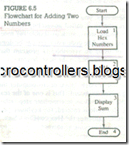
The steps listed in the problem analysis anti the sequence can be represented in a block diagram, called a flowchart. Figure 6.5 shows such a flowchart representing those steps. This is a simple flowchart, and the steps are self-explanatory. We will discuss flowcharting in the next section.

ASSEMBLY LANGUAGE PROGRAM

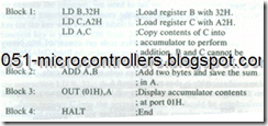
To write an assembly language program, we need to translate the blocks shown in the flowchart into Z80 operations and then into mnemonics. By examining the blocks in Figure 6.5, we can classify them into three types of Z80 operations: Block1and 3 are copy operations, Block 2 is an arithmetic operation, and Block

z80 Interfacing and programming-48_03

4 is a machine control operation. The translation of each block into mnemonics with comments is shown below.

z80 Interfacing and programming-49_03


FROM ASSEMBLY LANGUAGE TO HEX CODE

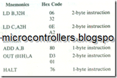
To convert the mnemonics into Hex code, we need to look up the code in the Z80 instruction set; this is called either manual or hand assembly. The Hex code is as follows:

z80 Interfacing and programming-49_07

STORING IN MEMORY AND CONVERTING FROM HEX CODE TO BINARY CODE

To store the program in R/W memory of a single-board microcomputer and display the output, we need to know the memory addresses and the output port address. Let us assume that R/W memory ranges from 2000H to 20FFH, and the system has an LED output port with the address 01H. To enter the program, the following steps are necessary:

1. Reset the system by pushing the RESET key.

2. Using Hex keys, enter the first memory address at which the program should be stored. Let us assume it is 2000H.

3. Enter each machine code by pushing Hex keys. For example, to enter the first machine code push 0, 6, and STORE keys. (The STORE key may be labelled differently in different systems.) When you push the STORE key, the program will store the machine code in memory location 2000H and upgrade the memory address to 2001H

4. Repeat Step 3 until the last machine code 76H

5. Reset the system.

Now the question is: How does the Hex code get converted into binary code? The answer lies with the Monitor program stored in the Read-Only Memory (or EPROM) of the microcomputer system. An important function of the Monitor program is to check the keys and convert Hex code into binary code. The entire process of manual assembly is shown in Figure 6.6.

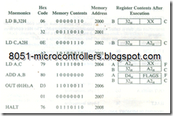
In this illustrative example, the program will be stored in memory as shown:

z80 Interfacing and programming-50_03

This program has nine machine codes and will require nine memory loca­tions to store the program. The critical concept to be emphasized here is that the microprocessor can understand and execute only the binary instructions (or data); everything else (mnemonics, Hex code, comments) are for the convenience of those who write and use the assembly language programs.

z80 Interfacing and programming-50_06

EXECUTING THE PROGRAM

To execute the program, we need to tell the microprocessor where the program begins by entering the memory address 2000H• Then, we can push the Execute key (or the key with a similar label) to begin the execution. As soon as the Execute function key is pushed, Z80 loads 2000H into the program counter, and the pro­gram control is transferred from the Monitor program to our program.

The microprocessor begins to read one machine code at a time, and when it fetches the complete instruction, it executes that instruction. For example, it will fetch the machine codes stored in memory locations 2000H and 2001H and execute the instruction LD B, 32H; thus, it loads 32H in register B as shown above in the last column of Register Contents. Next, it loads A2H into register C and copies A2H from register C into the accumulator A. It should be emphasized that the contents of register C are not changed in the copying process. When the ADD instruction is executed, the contents of A are changed to D4H, which is the sum of 32H and A2H• It continues to execute instructions until it fetches the HALT instruction.

6.3.2 Program Documentation or Writing Format

Program documentation is an important aspect of writing programs. The docu­mentation should be able to communicate what the program does and the logic underlying the program, so that it can be debugged and modified if necessary. For our illustrative program, a writing format based on assembler files (discussed in the next chapter) is shown here.

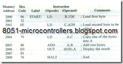
z80 Interfacing and programming-1_03

This writing format has five columns: Memory Address, Hex Code, Label, Instruction (Opcode and Operand), and Comments. Each column is described below in the context of a single-board computer.

Memory Addresses These are 16-bit addresses of the system’s R/W memory in which the binary code of the user program is stored. In the illustration, we as­sumed that the R/W memory in our system begins at the address 2000H, and we chose to store the program starting at the location 2000H; we could have chosen any other available memory block to store our program.

Hex Codes These are the hexadecimal codes of the Z80 mnemonics we looked up in the instruction set; they were entered in memory using the Hex keyboard of the single-board microcomputer system. The key monitor program of the sys­tem translates these Hex codes and stores the binary equivalents in the proper memory locations.

Labels They are used to identify a memory location. The program has one label:

START. This label is used for documentation; it indicates the beginning of the program. The labels are used to identify memory locations and will be especially useful for Jump instructions when we use assemblers to write programs (discussed in the next chapter).

Instructions These are the Z80 mnemonics representing the microprocessor op­erations. Each instruction is divided into two parts: opcode and operand.

Comments The comments are written as a part of the proper documentation of a program to explain or elaborate the purpose of the instruction used. They thus play a critical role in the user’s understanding of the logic behind a program. Because the i1lustrative program is very simple, the comments shown are either redundant or trivial, but in general comments should not merely describe the meaning of mnemonics.


OVERVIEW: Z80 INSTRUCTION SET par 2

Example 6.1

Write instructions in English-like statements to load the two data bytes 53H and F5H in registers A and B, respectively, and add the two bytes. Translate these statements into Z80 assembly language. I1lustrate the contents of registers af­fected in the programming model after the execution of each instruction and the status of the Carry and Zero flags.

z80 Interfacing and programming-44_11

This example does not show how to translate these instructions into binary code or how to execute them; this is discussed in the next section. Assuming these instructions are executed by the Z80 microprocessor, Figure 6.4(a) shows the con­tents of registers A and B after the execution of the first two instructions. The next instruction adds the contents of registers A and B; the sum is 148H• Figure 6.4(b) shows the accumulator with 48H and the CY flag set in the flag register. Please note that the flags are not affected by the Load or Copy instructions.

LOGIC OPERATIONS

The instructions related to logic operations can be divided into three groups logic functions (AND, OR, etc.), bit rotations or shifts and comp arisons (less than, greater than, and equal to) of data bytes.

· Logic Functions. Any 8-bit number, the contents of a register, or the contents of a memory location can be ANDed, ORed, or Exclusive ORed with the con­tents of the accumulator. The result is stored in the accumulator, and the flags are affected by the result.

Examples:

Ø Logically AND the contents of register B with the contents of the accumulator. → AND B

Ø Exclusive OR the contents of register B with the contents of the accumulator . →XOR B

· Shift and Rotate. Each bit in the accumulator, in the registers, or in memory can be shifted either left or right by one position.

Examples:

Ø Rotate the contents of the accumulator Right through Carry flag. → RRA

Ø Rotate left the contents of register B → RLC B

· Compare. Any 8-bit number, the contents of a register, or memory can be com­pared for equality, greater than, or less than with the contents of the accumu­lator. The result of the comparison is indicated by appropriate flags.

Examples:

Ø Compare the contents of register B with the contents of the accumulator. → CP B

Ø Compare the data byte 97 H with the contents of the accumulator. →CP 97H

BIT MANIPULATION

The bit manipulation instructions can be classified into two groups: bit test and bit set/reset.

· Bit Test- Any one of the eight bits in a register, accumulator, or memory can be verified as 0 or I, and the Z flag will be modified accordingly.

Example:

Ø Check bit D7 in register B. → BIT 7, B

· Bit Set/Reset– Anyone of the eight bits in a register, accumulator, or memory can be set or reset.

Example:

set bit d5 in the accumulator. →SET5, A

Reset bit D2 in register B.→RES2, B

BRANCHING OPERATIONS

This group of instructions alters the sequence of program execution either con­ditionally or unconditionally.

· Jump. The sequence of program execution can be altered either conditionally or unconditionally. When a conditional Jump instruction is used, the micropro­cessor checks the specified flag, and if the condition is true, the execution se­quence is altered; otherwise, the next instruction is executed. The destination location to which the program should be directed can be specified directly or relative to the contents of the program counter. These instructions are critical to the decision-making process in programming.

Examples:

Ø After an operation(such as an addition), → JP C, 2050H

if CY flag is set, jump to location 2050H

If Zero flag is not set, jump forward by 15 locations. →JR NZ, 0FH

· Call/Return. These instructions change the sequence of a program by calling a subroutine or returning from a subroutine. The conditional Call and Return in­structions check for appropriate flags.

Examples:

Ø Go to subroutine located at 2050H →CALL 2050H

Go to Subroutine located at 2070H if Z flag is set. → CALL Z, 2070H

· Restart. These instructions are used to change the program sequence to one of eight restart locations on memory page 00.The instructions are generally used with interrupts.

Example:

Ø Call location 0028H• → RST 28H

MACHINE CONTROL OPERATIONS

These instructions control microprocessor operations such as Halt and Interrupt.

Examples:

Ø Suspend execution of instruction. → HALT

Disable interrupts by resetting the Interrupt Enable flip-flops. → DI

6.2.3 Review of Important Concepts

Our intent here is to give you an overall view of the instruction set and the ca­pability of the Z80 microprocessor. The Z80 has 158 instruction types with 694opcodes. These numbers can be overwhelming and intimidating to a beginner. Fortunately, as you begin to use instructions, a logical pattern will begin to emerge. At this point, the important concepts to remember are as follows:

1. Each instruction has two parts: opcode and operand. The opcode specifies the task, and the operand specifies either data or where data are located.

2. Instructions can be classified into four groups according to their word length: one to four bytes.

3. In an instruction, when the data Source and the destination are explicitly spec­ified, the destination is shown first and the source second.

4. When an operand is a l6-bit address (or data).it is specified in a reversed order: the low-order byte first, followed by the high-order byte.

5. Instructions are stored in memory in binary format; the microprocessor neither reads nor understands mnemonics or hexadecimal numbers.

6. The number of memory locations required to store an instruction is determined by the word length. For example, a 3-byte instruction would require three memory locations.


6.2 OVERVIEW: Z80 INSTRUCTION SET

6.2 OVERVIEW: Z80 INSTRUCTION SET

The instruction set of a microprocessor determines the capability of its opera­tions, the power of its data manipulation, and the ease of programming it. Al­though it is necessary to have an overall view of the instruction set, our intent here is merely to acquaint you with the overall operations and capability of the Z80 microprocessor. As you progress through the chapters of Part II, you will be exposed to various instructions in more detail along with their applications.

The Z80 microprocessor has 158 instruction types; it includes all the instruc­tions of the Intel 8080 microprocessor and all but two of the 8085. As discussed in Chapter 1, each instruction has two parts: one is the task to be performed (such as Load, Add, and Jump), called the operation code (opcode); and the second identifies the data to be operated on, called the operand. First, we will examine various formats of these instructions in terms of number of bytes and then their classification according to their function.

6.2.1 Instruction Format

An instruction is a command to the microprocessor to perform a given task on specified data. The size of Z80 instructions ranges from one to four bytes; thus, the number of memory registers (locations) required to write (or store) them var­ies. For example, to write a 3-byte instruction into memory requires three mem­ory locations. Most opcodes (operation codes) are specified in one byte; however, some specialized opcodes require two bytes. The operand (or data) can be spec­ified in the following ways: 8-bit data, 16-bit data, registers, register pairs, I/O addresses, and memory addresses. The Z80 instruction set can be classified into four groups according to the length of an instruction: l-byte to 4-byte instructions. Because the Z80 is an 8-bit microprocessor, the terms "byte" and "word" are used synonymously.

1-BYTE INSTRUCTIONS

In a 1-byte instruction, the Opcode and the operand are included in the same byte as shown in the following examples.

z80 Interfacing and programming-40_03

In this instruction, the opcode LD is specified by the first two bits (01), and the operand registers A and B are specified by the remaining six bits. (The accu­mulator A is represented by 111 and register B by 000.) These bits are associated with the internal microoperations of the microprocessor and are not relevant for learning the instruction set.

2-BYTE INSTRUCTIONS

In a 2-byte instruction, the first byte specifies the opcode and the second byte specifies the operand (with exceptions of some Z80 two-opcode instructions).

z80 Interfacing and programming-40_06

3-BYTEINSTRUCTIONS

In a 3-byte instruction, the first byte specifies the opcode, and the following two bytes specify the 16-bit address or data in a reversed order: low-order byte followed by the high-order byte. For example:

z80 Interfacing and programming-40_09

4-BYTE INSTRUCTIONS

The descriptions given above for 2- and 3-byte instructions are valid for the in­structions compatible with the 8080 instructions. The Z80 instruction set, how­ever, includes numerous special-purpose instructions that are not compatible with the 8080 instruction set. An 8-bit microprocessor can have a maximum of 256 bit combinations; thus, its instruction set is limited to 256 operation codes. The 8080 has already used 242 combinations for its 72 different instructions, leaving only 14 combinations unused. However, the Z80 microprocessor needs many more combinations to use its additional registers (two index register alternate registers, interrupt vector, and refresh). This problem was resolved by designing 2­byte opcodes: unused opcodes combined with instruction opcodes.Z80 4-byte instructions are generally associated with index registers, as shown in the following example.

z80 Interfacing and programming-41_03


In this instruction, the opcode has two bytes, DD and 21. Now we can discuss various instructions according to their functional classification.

6.2.2 Z80 Instruction Set

The Z80 instruction set can be divided into six major categories as follows:

1. Data Copy (Transfer) or Load Operations

2. Arithmetic Operations

3. Logic Operations

4. Bit Manipulation

5. Branch Operations

6. Machine Control Operations

DATA COPY OR LOAD OPERATIONS

Copying data is one of the major functions the microprocessor needs to perform. The Z80 has numerous instructions that copy data from one location, called source, to another location, calIed destination, without modifying the contents of the source. In technical manuals, this function is quite often referred to as data transfer. However, since the term data transfer creates the impression that the contents of the source are destroyed, we prefer the term data copy. In this text, we have also used the terms Load, Read, and Write to describe data copy operations.

Figure 6.3 shows various categories of data copy operations. The Z80 has several instructions associated with each category, each of which, with its sub­divisions, is listed below with examples of instructions.
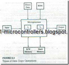
z80 Interfacing and programming-42_03

Data Copy Operations

1. From one register into another register

Copy the contents of register B into the accumulator.

LD, A, B; LD means Load

2. (a) Specific data byte into a register or a memory location.

Load registers B with the hexadecimal number 32. LD B, 32H

(b) Specific I6-bit data into a. regis­ter pair.

Load register pair HL with hexadeci­mal number 2050 . LD HL, 2050H

3. From a memory location into a reg­ister or vice versa.

Copy data from memory location 2080H into the accumulator. LD A, (2080H)*

4. (a) From an input port into the accumulator.

Read data from input port 01H and copy into the accumulator. IN A, (01H)*

(b) From the accumulator into an output port.

Write (send) the contents of the accu­mulator into port 07H• OUT (07H), * A

5. From microprocessor registers into stack memory locations and vice versa.

Copy the contents of register pair BC into defined stack memory locations. PUSH BC

6. Exchange contents between regis­ters. (This is a slightly different op­eration from data copy; this is a data exchange.)

Exchange the contents of general pur­pose registers (BC, DE, HL) with alter­nate registers. EXX

General characteristics of these data copy instructions can be listed as follows:

1. In data copy operations, the contents of the source are copied into the desti­nation without affecting the contents of the source (except in Exchange instructions).

2. In an operand, the destination is specified first, followed by the source. For ex­ample, in the instruction LD A, B (copy the contents of B into A), the source is register B and the destination is the accumulator. This may appear backward be­cause the flow is generally assumed to be from left to right, the way we read text.

3. The memory and I/O addresses are enclosed in parentheses.

4. In some instructions, operand is implicit (for example, EXX).

5. Data copy instructions do not affect flags.

ARITHMETIC OPERATIONS

The Z80 instruction set includes four types of arithmetic operations:addition,subtraction,increment/decrement, and I’s and 2’s complement. In 8-bit arithmetic operations, the accumulator is generally assumed to be one of the operands (with the exception of increment/decrement instructions).

· Addition. Any 8-bit number, or the contents of a register, or the contents of a memory location can be added to the contents of the accumulator. The result of the addition is stored in the accumulator, and the flags are affected by the result No two other 8-bit registers can be added directly; for example, the contents of register B cannot be added directly to the contents of register C.

z80 Interfacing and programming-43_03

· Subtraction. Any 8-bit number, or the contents of a register, or the contents of a memory location can be subtracted from the contents of accumulator, the subtraction is performed in 2’s complement, and the result is stored in the accumulator. The result modifies the flags, and if the result is negative, it. is ex­pressed in 2’s complement. The following mnemonics indicate that the accu­mulator is implicitly assumed as one of the operands.

z80 Interfacing and programming-44_03

· Increment/Decrement. The 8-bit contents of a register (including the accumula­tor) or a memory location can be incremented or decremented by 1. Similarly, the l6-bit contents of a register pair (such as HL) can be incremented or decremented by 1. Unlike Add and Subtract, these operations can be performed in any of the registers. The instructions related to 8-bit contents affect flags (except Carry); on the other hand, instructions related to l6-bit contents do not affect any flags.

z80 Interfacing and programming-44_06

l’s and 2’s Complement. The contents of the accumulator can be complemented (I’s or 2’s complement), and the result is stored in the accumulator. Some flags are affected by the result. These instructions assume that the operand is the accumulator.

z80 Interfacing and programming-44_08