6.4 FLOWCHARTING
A flowchart is a graphic representation of the logic and sequence of tasks to be performed. A flowchart should assist in clarifying one’s thinking process and communicate the programmer’s approach and logic in writing the program.
Flowcharting is an art; how much detail it should include requires a subjective decision. At one level, the flowchart includes only the functions to be performed without any reference to a particular microprocessor; at another level, the functions of registers being used are specified in detail. However, it should not duplicate the instructions in the program in a graphic format; this would defeat the whole purpose of drawing the flowchart. It should simply represent a logical approach and sequence of steps in solving the problem.
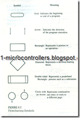
The six symbols commonly used in flowcharting are shown in Figure 6.7. We have already used three symbols in Figure 6.5. The fourth symbol, shown by the diamond shape, represents the decision-making block. It is used when data conditions need to be checked and the program sequence has to be altered. This symbol is i1lustrated in Figure 6.8. The fifth symbol, a double-sided rectangle, represents a predetermined process such as a subroutine (discussed in Chapter 10). The last symbol, a circle with an arrow, is used to show continuation of the flowchart to a different column or to a different page.
Example 6.2
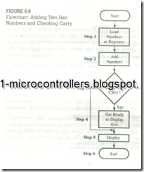
Draw a flowchart to represent the following problem. Load two Hex bytes into Z80 registers, and add the bytes. If the sum is larger than 8 bits, display O/H as the overload condition at port PORT7; otherwise, display the sum at the output port.
The problem can be divided into the following steps.
1. Load bytes into Z80 registers.
2. Add the bytes. .
3. Check the sum.
4. If the sum> FFH, display 01H at the output port.
5. If the sum < FFH, display the sum at the output port.
The steps listed in Example 6.2 and the sequence can be represented by the flowchart shown in Figure 6.8. The first two blocks can be easily understood. The third block, shown by the diamond shape, is a decision-making block. In this block the result is checked by examining the CY flag, and the program execution is altered accordingly. If the CY flag is set, the result is larger than FFH and the program execution goes to the next block. It loads 01 H and displays it at the output port. If the answer to the question in the decision block is "No," the sum is less than FF. The program sequence is then altered; it bypasses Block 4 and displays the sum at the output port.
An interesting question is: Can we interchange the answers "Yes" and "No" at the decision-making block? That is, can the program sequence be changed if CY is set? This is given as a problem at the end of the chapter: you may find that the resulting flowchart will have two end points.

