Flags and Decision Making

Flags and Decision Making

As described in Chapter 6, the Z80 architecture includes six flags, which are flip-flops that are set or reset after the execution of arithmetic and logic operations, with some exceptions. Four of the flags (S, Z, P/V, and CY) can be used by the programmer for decision making in conjunction with Jump and Call instructions; the remaining two (H, N) are used internally by the microprocessor for BCD arith­metic. The thorough understanding of flags is critical to writing assembly language programs.

In many ways the flags are like signs on an interstate highway that help drivers in decision making. A driver sees one or more signs at a time, but contin­ues along the highway ignoring the signs until the appropriate sign is found, and then he or she changes direction or takes an exit. Flags function similarly as signs of data conditions. After an operation, one or more flags are set (or reset) and can be used to change the direction of program sequence by using Jump instructions (discussed in the next section). The following illustrations from Example may clarify some of the critical issues.

1. In Example, Instruction 5 sets the Sign flag and resets the other flags. However, the Sign flag can be ignored because the numbers loaded into reg­isters are unsigned numbers. The Sign flag is relevant when the programmer is dealing with signed numbers.

2. Instruction 7 sets the Carry flag and resets the other flags. If the programmer is adding numbers and is interested in finding the total, the Carry flag must be used to test for a sum larger than an 8-bit number.

3. Another important observation that can be made after the execution of Instruc­tion 7 is that the flags set by Instruction 5 are altered by Instruction 7. Thus, if the programmer is interested in making a decision based on the Sign flag, it should be made before that flag is altered by another operation.

Signed Numbers and Flags

The microprocessor is incapable of understanding a + or – sign unless the sign is represented in the form of binary digits. Therefore, in 8-bit microprocessors, bit D7 is reserved for the sign by the user when signed numbers are used in arith­metic operations. For a positive number, bit D7 is 0, and for a negative number, D7 is set to 1; the remaining seven bits represent the magnitude of a number. If a number is negative, it is represented in 2’s complement. In an 8-bit microprocessor, the largest positive number is 0111 1111 (7FH = + 12710), and the largest negative number is 1000 0000 (80H = -12810).

The Z80 microprocessor has two flags to indicate the status of the arithmetic results in signed numbers: Sign and Overflow. After an arithmetic (or logical) operation, if bit D7 = 1, the Sign flag is set, and if D7 = 0, the Sign flag is reset. However, this flag can be misleading when the result of an addition exceeds the magnitude 7FH or that of the subtraction exceeds 80H. These conditions are known as overflow and are indicated by the P/V flag.

The P/V flag is a dual-purpose flag; in logical operations it indicates parity, and in arithmetic operations it indicates an over flow. In arithmetic operations, if the sum of two positive numbers exceeds 7F, bit D7 becomes 1, indicating a neg­ative number. However, the Z80 sets the P/V flag to indicate the error in the result. The critical point to remember is that the Z80 does not know whether the numbers are signed, unsigned, or just individual digits. The interpretation of the flags is the responsibility of the user.

Example

Add two signed numbers: + 29H and + 76H. Indicate the status of the flags S, P/V, and CY if the operation is performed by the Z80 microprocessor. Explain how. The flags are affected if the numbers are unsigned.

Solution

Assembly Language Programming (6)


CY = 0 because the sum does not exceed FFH,

S = 1 because D7 = 1, and

P/V =1 because the sum exceeds 7FH.

In this addition of two positive numbers, the sign flag erroneously indicates that the sum is negative; however, the overflow flag (P/V) suggests that the result has an overflow from bit D6 and that the result is therefore inaccurate. The user must check the P/V flag and correct the sum.

If these numbers were unsigned numbers, the interpretation of the result would therefore be different; the user should ignore the S and P/V flags and check for the CY flag. In this example, the sum is 9FH with no carry.

­Another common misunderstanding is that bit D0 in the result 9FH is 1; therefore, bit D0 in the flag register must be 1, thus setting the CY flag. There is no relationship between bit D0 of a result and bit D0 of the flag register.

 

ARITHMETIC OPERATIONS

ARITHMETIC OPERATIONS

The Z80 microprocessor performs various arithmetic operations such as addition, subtraction, increment/decrement, and I’s and 2’s complement. Most of these op­erations are concerned, with 8-bit operands. The instruction set also includes some 16-bit operations that will be discussed in later chapters. (See Appendix A for a complete alphabetical listing of the Z80 instruction set and how flags are affected by the instructions.)

Addition and Subtraction

The addition and subtraction operations are performed in relation to contents of the accumulator. We focus here on three types of operands: register contents, 8-bit data, and memory contents.

Opcode

Operand

Bytes

Description

ADD

A, r

1

Add contents of register r to the contents of the accumulator, and store the result in the accumulator.

ADD

A, 8-bit

2

Add 8-bit data directly to the accumulator.

ADD

A,(HL)

1

Add memory contents to the accumulator.

SUB

R

1

Subtract contents of register r from the accumulator.

SUB

8-bit

2

Subtract 8-bit data from the accumulator.

SUB

(HL)

1

Subtract memory contents from the accumulator.

General Characteristics

These arithmetic instructions:

1. Assume that the accumulator is one of the operands.

2. Modify all the flags according to the result of the operation.

3. Place the result in the accumulator.

4. Do not affect the contents of the operand register or memory.

Increment/Decrement Instructions

The following instructions are special types of arithmetic instructions; they incre­ment or decrement the contents of the operand by one. These instructions are generally used in counting and indexing.

Opcode

Operand

Bytes

Description

INC

r

1

Increment the contents of register r.

INC

(HL)

1

Increment the contents of memory.

INC

rp

1

Increment the contents of register pair rp

(Register pairs are BC, DE, HL, and SP).

DEC

r

1

Decrement the contents of register r.

DEC

(HL)

1

Decrement the contents of memory.

DEC

rp

1

Decrement the contents of register pair rp.

General Characteristics

1. In these instructions, the operand can be any of the 8-bit registers r, memory, or register pairs rp. The result is stored back into the same operand register.

2. The instructions dealing with 8-bit registers affect all the flags except the Carry (CY) flag.

3. The instructions dealing with register pairs do not affect any flags. This is im­portant to remember when a register pair is used as a 16-bit counter.

I’s and 2’s Complement Instructions

The Z80 instruction set includes the following instructions that perform comple­ment operations with the contents of the accumulator. The addressing mode is implied; the accumulator is implied as the operand.

Opcode

Operand

Bytes

Description

CPL

1

Invert each bit of the accumulator. This can also be classified as the NOT function. No flags (except H and N) are affected.

NEG

2

Subtract the contents of the accumulator from 00; this is equivalent to 2’s complement of the number in the accumulator. This instruction affects all the flags.

Example

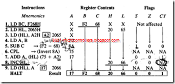
Load two unsigned numbers F2H and 68H in registers B and C, respectively, and store A2H in memory location 2065H, using the HL register as a memory pointer. Subtract 68H from F2H complement the result, and add A2H from memory. Store the final answer in memory location 2066H. Show register contents and the status of S (Sign), Z (Zero), and CY (Carry) flags as each instruction is being executed.

Assembly Language Programming (5)

Description

l. The first instruction loads register BC with the given bytes. This could be achieved by using two separate load instructions for each register, but loading a register Pair is slightly more efficient

2. The second instruction sets up HL as a memory pointer for location 2065H, and the third instruction loads A2H into the memory location indicated by HL.

3. To subtract C from B, it is necessary to copy the contents of B into the accu­mulator (instruction 4).

4. Instruction I through 4 are all data copy instructions; they do not affect flags. All the flags will remain in their initial conditions before the program is executed.

5. Instruction 5 performs the subtraction in 2’s complement and places 8AH in the accumulator as shown below. The subtraction method using 2’s Comple­ment involves three steps: (1) Find 2’s complement of the subtrahend, (2) Add the 2’s complement to the minuend, and (3) Complement CY. (Refer to Appen­dix B if you are unfamiliar with the technique.)

The result of this subtraction sets the Sign flag and resets the Zero and Carry flags. However, the result is not a negative number. After an arithmetic oper­ation, if bit D7 = 1, the Sign flag is set. In this subtraction, the Sign flag should be ignored because data bytes are not signed numbers

6. The instruction CPL inverts the contents of the accumulator 8AH; the result is 75H. This instruction does not affect any flags, so the flags set by the previous instruction are preserved.

1 0 0 0 1 0 1 0 (8AH) → 0 1 1 1 0 1 0 1 (75H)

7. Instruction 7 adds A2H from the memory location pointed to by HL to the accumulator contents (75H). The result is 117H. The instruction places 17H into the accumulator, sets the CY flag. and resets the S and Z flags.

8. Instruction 8 increments HL to point to the next location 2066H, and the next instruction stores the result in the memory location 2066H.

9. The HALT is a machine control instruction; it does not affect any registers or the flags. The final result is shown in the box.


Data Copy Between Accumulator and I/Os

Data Copy Between Accumulator and I/Os

In the Z80 instruction set, input and output devices are identified by 8-bit addresses, The set includes several instructions that can read data from an in put device (also known as input port) and write data into an output device (or output port). Two of these I/O instructions are described here:

Opcode

Operand

Bytes

Description

IN

A, (8-bit)

2

Read data from an input port into the accumulator.

OUT

(8-bit), A

2

Write data to an output port from the accumulator.

General Characteristics

I. These I/O instructions do not affect flags. (Some Z80 l/O instructions do affect flags; they are discussed later.)

2. The I/O instructions have 8-bit operands; thus, the Z80 is capable of addressing 256 input and 256 output ports with addresses from 00 to FFH.

3. The 8-bit I/O addresses are enclosed in parentheses similar to those of memory addresses.

Example

Read the switches connected to the input port 01H . Display the read­ing at the LED output port 07H and store it in memory location 2060H.

Solution

Instructions are as follows:

Opcode

Operand

Comments

IN OUT

A, (01H)

(07H), A

;READ INPUT SW ITCHES

;DISPLAY SWITCH READING AT OUTPUT PORT

LD HALT

( 2060H ), A

;STORE SW ITCH READ I NG IN MEMORY


Assembly Language Programming (4)

Description

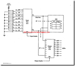
1. shows that the switch positions of the input port 01H provide the reading 0 1 0 0 1111 (4FH). The first instruction reads the switch positions and places the reading in the accumulator.

2. The OUT instruction sends the accumulator contents to the output port 07" and displays the corresponding LEDs

3. The last instruction stores the accumulator contents in memory location 2060H.


DATA COPY (LOAD) OPERATIONS

DATA COPY (LOAD) OPERATIONS

In this section, we focus on three types of data copy operations: data copy related to microprocessor registers, memory, and I/Os. Instructions frequently used are illustrated below, and the Z80 block transfer instruction will be discussed later in the chapter. In addition, one machine control instructionــــHALTــــis introduced; this instruction is necessary to indicate the end of a program.

Data Copy (Load) Among Registers

In this group, we have three types of instructions: data copy from one register to another, loading 8-bit data into a register, and loading 16-bit data into a register pair.

Opcode

Operand

Bytes

Addressing Modes

Description

LD

Rd , rs

Example:

1

LD B,C

Register

Copy data from source register rs to destination register rd. In this mode, operand is a part of the Opcode.

LD

r†, 8-bit

Example:

2

LD B,32H

Immediate

Load 8-bit data of the second byte into the specified register. In this mode, the sec­ond byte is the operand.

LD

rp, 16-bit

Example:

3

LD HL,1850H

Immediate Extended

Load 16 bits into the specified register pair. In this mode, two bytes following the opcode are the operands.

LD

rx , 16- bit

Example:

4

LD IX,2050H

Immediate Extended

Load 16 bits into the specified index register.

HALT

1

This is a machine con­trol instruction. The processor stops exe­cuting and enters into Wait state.

General Characteristics

1. Copy (Load) instructions do not affect flags.

2. The operands of copy instructions specify a destination register first, followed by a source register; they are separated by a comma.

3. The data byte is copied without modifying the contents of a source register.

4. A 16-bit operand is stored in two consecutive memory locations in the reversed order: the low-order byte first, followed by the high-order byte.

5. The instructions related to the index registers IX and IY have two-byte Opcodes.

6. Data cannot be loaded directly into the flag register, program counter (PC), and alternate registers: the immediate addressing mode is not available for these registers.

Assembly Language Programming (Assembly Language Programming)

Description

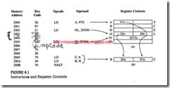
1. The first instruction LD A, 97H is a 2-byte instruction; the opcode 3EH and the operand 97H are stored in the first two memory locations. This instruction loads: 97H into the accumulator .

2. The second instruction is a 3-byte instruction that loads 16-bit data (2050H) into the HL registers. The low-order byte (50H) is stored first in memory location 2003H, followed by the high-order byte (20H).

3. The third instruction (IX, 2075H) is a 4-byte instruction; it has a 2- byte opcode (DD and 21). This instruction loads 16-bit data (2075H) into the index register IX.

4. The remaining two instructions are 1-byte instructions; they copy data from one register to another as shown .It is important to note that the copy operations do not destroy the contents of the source registers. Fig­ure 8.1 shows that registers A and H retain their contents after the copy operations.

5. The last instruction (HALT) is a machine control instruction; it forces the machine into the Wait state


Introduction to Z80 Instructions and Programming Techniques

Introduction to Z80 Instructions and Programming Techniques


farbfernseher_31_cm_nec_autocolor

When a microcomputer is asked to execute a program stored in its memory, it reads one in­struction at a time and performs the task spec­ified by the instruction. Each instruction in the program is a command, in binary, to the micro­processor to perform an operation. In Chap­ter 6, we examined briefly the Z80 instruction set and its capability. In this chapter, we will introduce a few selected instructions and illus­trate them with examples. These instructions are selected from three groups: data copy, arith­metic, and branch operations.

A computer is at its best, relative to hu­man capability, when it is asked to repeat such. Simple tasks as adding or copying. The programming techniquesــــ such as looping, index­ing, and countingــــ necessary to perform such tasks are introduced and illustrated with two programs. This chapter also includes a brief dis­cussion of debugging programs.

Finally, a group of special Z80 instructions that perform multiple tasks are introduced with illustrative examples.

OBJECTIVES

· Explain the functions of data copy instruc­tions and how the contents of the source register and the destination registers are affected.

· List four types of data copy operations and explain the term addressing mode.

· Explain how a memory address is specified to copy data from and to a memory register.

· Explain how data are transferred from and to I/O devices.

· Explain the functions of arithmetic instruc­tions (ADD, SUB, INC, DEC) and how flags are affected by these instructions.

· Write a set of commands using data copy and arithmetic instructions to perform a given task.

· Explain the functions of unconditional and conditional jump instructions and how they are used for decision making.

· Draw a flowchart of a conditional loop to il­lustrate the indexing and counting tech­niques.

· List the seven blocks of a generalized flow­chart illustrating data acquisitions and data processing.

· Write a program to copy data from one block of memory to another block including the case of overlapping blocks.

· Write a program to perform arithmetic oper­ations on given data stored in memory.

· List the types of errors that frequently occur in writing assembly language programs and in hand assembling the code. Recognize the er­rors in a given program.

· List Z80 special instructions and explain how they provide more flexibility and improve ef­ficiency in writing Z80 programs.

· Modify the previously written programs us­ing the Z80 special instructions.


Problems on Moving Data

Problems

Write programs that will accomplish the desired tasks listed below, using as few lines of code as possible. Use only opcodes that have been covered up to this chapter. Comment on each line of code.

1. Place the number 3Bh in internal RAM locations 30h to 32h.

2. Copy the data at internal RAM location Flh to R0 and R3.

3. Set the SP at the byte address just above the last working register address.

4. Exchange the contents of the SP and the PSW.

5. Copy the byte at internal RAM address 27h to external RAM address 27h.

6. Set Timer 1 to A23Dh.

7. Copy the contents of DPTR to registers R0 (DPL) and R1 (DPH).

8. Copy the data in external RAM location 0123h to TL0 and the data in external RAM location 0234h to TH0.

9. Copy the data in internal RAM locations 12h to 15h to internal RAM locations 20h to 23h: Copy 12h to 20h. 13h to 21h, etc.

10. Set the SP register to 07h and PUSH the SP register on the stack; predict what number is PUSHed to address 08h.

11. Exchange the contents of the B register and external RAM address 02CFh.

12. Rotate the bytes in registers R0 to R3; copy the data in R0 to R 1, R 1 to R2, R2 to R3, and R3 to R0.

13. Copy the external code byte at address 007Dh to the SP.

14. Copy the data in register R5 to external RAM address 032Fh.

15. . Copy the internal code byte at address 0300h to external RAM address 0300h.

16. Swap the bytes in timer 0; put TL0 in TH0 and TH0 in TL0.

17. Store DPTR in external RAM locations 0123h (DPL) and 02BCit (DPH).

18. Exchange both low nibbles of registers R0 and R1; put the low nibble of R0 in R1, and the low nibble of R1 in R0.

19. Store the contents of register R3 at the internal RAM address contained in R2. (Be sure the address in R2 is legal.)

20. Store the contents of RAM location 20h at the address contained in RAM location 08h.

21. Store register A at the internal RAM location address in register A.

22. Copy program bytes 0100h to 0102h to internal RAM locations 20h to 22h.

23. Copy the data on the pins of port 2 to the port 2 latch.

24. PUSH the contents of the B register to TMOD.

25. Copy the contents of external code memory address 0040h to IE.

26. Show that a set of XCH instructions executes faster than a PUSH and POP when saving the contents of the A register,


Summary of Moving Data

Summary

The opcodes that move data between locations within the 8051 and between the 8051 and external memory have been discussed. The general form and results of these instructions are as follows.

Instruction Type

Result

MOV destination, source

Copy data from the internal RAM source address to the internal RAM destination address

MOVC A, source

Copy internal or external program memory byte from the source to register A

MOVX destination, source

Copy byte to or from external RAM to register A

PUSH source

Copy byte to internal RAM stack from internal RAM source

pop destination

Copy byte from internal RAM stack to internal RAM destination

XCH A, source

Exchange data between register A and the internal RAM source

XCHD A, source

Exchange lower nibble between register A and the internal RAM source

There are four addressing modes: an immediate number, a register name, a direct internal RAM address, and an indirect address contained in a register.


Example Programs

Example Programs

Programming is at once a skill and an art. Just as anyone may learn to play a musical instrument after sufficient instruction and practice. so may anyone learn to program a computer. Some individuals. however. have a gift for programming that sets them apart from their peers with the same level of experience. just as some musicians are more tal­ented than their contemporaries.

Gifted or not. you will not become adept at programming until you have written and rewritten many programs. The emphasis here is on practice; you can read many books on how to ride a bicycle, but you do not know how to ride until you do it.

If some of the examples and problems seem trivial or without any "real-world" appli­cation. remember the playing of scales on a piano by a budding musician. Each example will be done using several methods; the best method depends upon what resource is in short supply. If programming time is valuable. then the best program is the one that uses the fewest lines of code; if either ROM or execution time is limited. then the program that uses the fewest code bytes is best.

¨ EXAMPLE PROBLEM 3.1

Copy the byte in TCON to register R2 using at least four different methods.

· Method1: Use the direct address for TCON (88h) and register R2.

Mnemonic Operation

MOV R2.88h Copy TCON to R2

· Method 2: Use the direct addresses for TCON and R2.

Mnemonic Operation

MOV 02h.88h Copy TCON to direct address 02h (R2)

· Method 3: Use R1 as a pointer to R2 and use the address of TCON.

Mnemonic Operation

MOV R1,#02h Use R1 as a pointer to R2

MOV @R1 .88h Copy TCON byte to address in R1 (02h = R2)

· Method 4: Push the contents of TCON into direct address 02h (R2).

Mnemonic Operation

MOV 81h.#01h Set the SP to address 01 h in RAM

PUSH 88h Push TCON (88h) to address 02h (R2)

¨ EXAMPLE PROBLEM 3.2

Set timer T0 to an initial setting of 1234h.

· Method 1: Use the direct address with an immediate number to set THO and TLO.

Mnemonic Operation

MOV 8Ch,#12h Set TH0 to 12h

MOV 8Ah,#34h Set TL0 to 34h

Totals: 6 bytes, 2 lines

· Method 2: Use indirect addressing with RO for TLO and RI for THO.

Mnemonic Operation

MOV R0,#8Ah Copy 8Ah, the direct address of TL0, to R0

MOV R1,#8Ch Copy 8Ch, the direct address of TH0, to R1

MOV @R0,#34h Copy 34h to TLO

MOV @R1,#12h Copy 12h to THO

Totals: 8 bytes, 4 lines

The first method is also the better method in this example.

¨ EXAMPLE PROBLEM 3.3

Put the number 34h in registers R5, R6, and R7.

· Method 1: Use an immediate number and register addressing.

Mnemonic Operation

MOV R5,#34h Copy 34h to R5

MOV R6,#34h Copy 34h to R6

MOV R7,#34h Copy 34h to R7

Totals: 6 bytes, 3 lines

· Method 2: Since the number is the same for each register, put the number in A and MOV A to each register.

Mnemonic Operation

MOV A,#34h Copy a 34h to A

MOV R5,A Copy A to R5

MOV R6,A Copy A to R6

MOV R7,A Copy A to R7

Totals: 5 bytes, 4 lines

· Method 3: Copy one direct address to another.

Mnemonic Operation

MOV R5,#34h Copy 34h to register R5

MOV 06h,05h Copy R5 (add 05) to R6 (add 06)

MOV 07h,06h Copy R6 to R7

Totals: 8 bytes, 3 lines

¨ EXAMPLE PROBLEM 3.4

Put the number 80h in RAM locations 30h to 34h.

· Method 1: Use the immediate number to a direct address:

Mnemonic Operation

MOV 30h,#8Dh Copy the number 80h to RAM address 30h

MOV 31h,#8Dh Copy the number 80h to RAM address 31 h

MOV 32h,#8Dh Copy the number 8Dh to RAM address 32h

MOV 33h,#8Dh Copy the number 80h to RAM address 33h

MOV 34h,#8Dh Copy the number 80h to RAM address 34h

Totals: 15 bytes,5 lines

· Method 2: Using the immediate number in each instruction uses bytes; use a register to hold the number:

Mnemonic Operation

MOV A,#80h Copy the number 80h to the A register

MOV 30h,A Copy the contents of A to RAM address 30h

MOV 31h,A Copy the contents of A to the remaining addresses

MOV 32h,A

MOV 33h,A

MOV 34h,A Totals: 12 bytes, 6 lines

· Method 3: There must be a way to avoid naming each address; the PUSH opcode can increment to each address:

Mnemonic Operation

MOV 30h,#8Dh Copy the number 8Dh to RAM address 30h

MOV 81h,#3Dh Set the SP to 30h

PUSH 30h Push the contents of 30h (=8Dh) to address 31h

PUSH 30h Continue pushing to address 34h

PUSH 30h

PUSH 30h Totals: 14 bytes, 6 lines

COMMENT

Indirect addressing with the number in A and the indirect address in R 1 could be done; how­ever, R 1 would have to be loaded with each address from 30h to 34h. Loading R 1 would take a total of 17 bytes and 11 lines of code. Indirect addressing is advantageous when we have opcodes that can change the contents of the pointing registers automatically.


Data Exchanges

Data Exchanges

MOV, PUSH, and POP opcodes all involve copying the data found in the source address to the destination address; the original data in the source is not changed. Exchange instruc­tions actually move data in two directions: from source to destination and from destination to source. All addressing modes except immediate may be used in the XCH (exchange) opcodes:

Mnemonic

Operation

XCH A,Rr

Exchange data bytes between register Rr and A

XCH A,add

Exchange data bytes between add and A

XCH A,@Rp

Exchange data bytes between A and address in Rp

XCHD A,@Rp

Exchange lower nibble between A and address in Rp

Exchanges between A and any port location copy the data on the port pins to A, while the data in A is copied to the port latch. Register A is used for so many instructions that the XCH opcode provides a very convenient way to "save" the contents of A without the necessity of using a PUSH opcode and then a POP opcode.

The following table shows examples of data moves using exchange opcodes:

Mnemonic

Operation

XCH A,R7

Exchange bytes between register A and register R7

XCH A,0F0h

Exchange bytes between register A and register B

XCH A,@R1

Exchange bytes between register A and address in R 1

XCHD A,@R1

Exchange lower nibble in A and the address in R 1

CAUTION

All exchanges are internal to the 8051.

All exchanges use register A.

When using XCHD, the upper nibble of A and the upper nibble of the address location in Rp do not change.

This section concludes the listing of the various data moving instructions; the remain­ing sections will concentrate on using these opcodes to write short programs.


PUSH and POP Opcodes

PUSH and POP Opcodes

The PUSH and POP opcodes specify the direct address of the data. The data moves between an area of internal RAM, known as the stack, and the specified direct address. The stack pointer special-function register (SP) contains the address in RAM where data from the source address will be PUSHed, or where data to be POPed to the destination address is found. The SP register actually is used in the indirect addressing mode but is not named in the mnemonic. It is implied that the SP holds the indirect address when­ever PUSHing or POPing. Figure 3.3 shows the operation of the stack pointer as data is PUSHed or POPed to the stack area in internal RAM.

A PUSH opcode copies data from the source address to the stack. SP is incremented by one before the data is copied to the internal RAM location contained in SP so that the data is stored from low addresses to high addresses in the internal RAM. The stack grows up in memory as it is PUSHed. Excessive PUSHing can make the stack exceed 7Fb (the top of internal RAM). after which point data is lost.

A POP opcode copies data from the stack to the destination address. SP is decre­mented by one after data is copied from the stack RAM address to the direct destination to ensure that data placed on the stack is retrieved in the same order as it was stored.

The PUSH and POP opcodes behave as explained in the following table:

Mnemonic

Operation

PUSH add

Increment SP; copy the data in add to the internal RAM address contained in SP

POP add

Copy the data from the internal RAM address contained in SP to add; decrement the sp


Pages-from-Hardware---The-8051-Microcontroller-Architecture,-Programming-and-Applications-1991_Page_09_Image_0001_03


The SP register is set to 07h when the 8051 is reset, which is the same direct address in internal RAM as register R7 in bank 0. The first PUSH opcode would write data to R0 of bank 1. The SP should be initialized by the programmer to point to an internal RAM address above the highest address likely to be used by the program.

The following table shows examples of PUSH and POP opcodes:

Mnemonic

Operation

MOV 81h,#30h

Copy the immediate data 30h to the SP

MOV R0, #0ACh

Copy the immediate data ACh to R0

PUSH 00h

SP = 31h; address 31h contains the number ACh

PUSH 00h

SP = 32h; address 32h contains the number ACh

POP 0lh

SP = 31 h; register R 1 now contains the number Ach

POP 80h

SP = 30h; port 0 latch now contains the number ACh

CAUTION

When the SP reaches FFh it "rolls over" to 00h (R0).

RAM ends at address 7Fh; PUSHes above 7Fh result in errors.

The SP is usually set at addresses above the register banks.

The SP may be PUSHed and POPed to the stack.

Note that direct addresses, not register names, must be used for most registers. The stack mnemonics have no way of knowing which bank is in use.