ARITHMETIC OPERATIONS
The Z80 microprocessor performs various arithmetic operations such as addition, subtraction, increment/decrement, and I’s and 2’s complement. Most of these operations are concerned, with 8-bit operands. The instruction set also includes some 16-bit operations that will be discussed in later chapters. (See Appendix A for a complete alphabetical listing of the Z80 instruction set and how flags are affected by the instructions.)
Addition and Subtraction
The addition and subtraction operations are performed in relation to contents of the accumulator. We focus here on three types of operands: register contents, 8-bit data, and memory contents.
|
Opcode |
Operand |
Bytes |
Description |
|
ADD |
A, r |
1 |
Add contents of register r to the contents of the accumulator, and store the result in the accumulator. |
|
ADD |
A, 8-bit |
2 |
Add 8-bit data directly to the accumulator. |
|
ADD |
A,(HL) |
1 |
Add memory contents to the accumulator. |
|
SUB |
R |
1 |
Subtract contents of register r from the accumulator. |
|
SUB |
8-bit |
2 |
Subtract 8-bit data from the accumulator. |
|
SUB |
(HL) |
1 |
Subtract memory contents from the accumulator. |
General Characteristics
These arithmetic instructions:
1. Assume that the accumulator is one of the operands.
2. Modify all the flags according to the result of the operation.
3. Place the result in the accumulator.
4. Do not affect the contents of the operand register or memory.
Increment/Decrement Instructions
The following instructions are special types of arithmetic instructions; they increment or decrement the contents of the operand by one. These instructions are generally used in counting and indexing.
|
Opcode |
Operand |
Bytes |
Description |
|
INC |
r |
1 |
Increment the contents of register r. |
|
INC |
(HL) |
1 |
Increment the contents of memory. |
|
INC |
rp |
1 |
Increment the contents of register pair rp (Register pairs are BC, DE, HL, and SP). |
|
DEC |
r |
1 |
Decrement the contents of register r. |
|
DEC |
(HL) |
1 |
Decrement the contents of memory. |
|
DEC |
rp |
1 |
Decrement the contents of register pair rp. |
General Characteristics
1. In these instructions, the operand can be any of the 8-bit registers r, memory, or register pairs rp. The result is stored back into the same operand register.
2. The instructions dealing with 8-bit registers affect all the flags except the Carry (CY) flag.
3. The instructions dealing with register pairs do not affect any flags. This is important to remember when a register pair is used as a 16-bit counter.
I’s and 2’s Complement Instructions
The Z80 instruction set includes the following instructions that perform complement operations with the contents of the accumulator. The addressing mode is implied; the accumulator is implied as the operand.
|
Opcode |
Operand |
Bytes |
Description |
|
CPL |
1 |
Invert each bit of the accumulator. This can also be classified as the NOT function. No flags (except H and N) are affected. |
|
|
NEG |
2 |
Subtract the contents of the accumulator from 00; this is equivalent to 2’s complement of the number in the accumulator. This instruction affects all the flags. |
Example
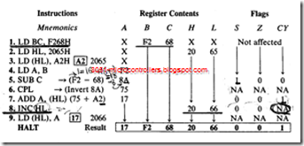
Load two unsigned numbers F2H and 68H in registers B and C, respectively, and store A2H in memory location 2065H, using the HL register as a memory pointer. Subtract 68H from F2H complement the result, and add A2H from memory. Store the final answer in memory location 2066H. Show register contents and the status of S (Sign), Z (Zero), and CY (Carry) flags as each instruction is being executed.
Description
l. The first instruction loads register BC with the given bytes. This could be achieved by using two separate load instructions for each register, but loading a register Pair is slightly more efficient
2. The second instruction sets up HL as a memory pointer for location 2065H, and the third instruction loads A2H into the memory location indicated by HL.
3. To subtract C from B, it is necessary to copy the contents of B into the accumulator (instruction 4).
4. Instruction I through 4 are all data copy instructions; they do not affect flags. All the flags will remain in their initial conditions before the program is executed.
5. Instruction 5 performs the subtraction in 2’s complement and places 8AH in the accumulator as shown below. The subtraction method using 2’s Complement involves three steps: (1) Find 2’s complement of the subtrahend, (2) Add the 2’s complement to the minuend, and (3) Complement CY. (Refer to Appendix B if you are unfamiliar with the technique.)
The result of this subtraction sets the Sign flag and resets the Zero and Carry flags. However, the result is not a negative number. After an arithmetic operation, if bit D7 = 1, the Sign flag is set. In this subtraction, the Sign flag should be ignored because data bytes are not signed numbers
6. The instruction CPL inverts the contents of the accumulator 8AH; the result is 75H. This instruction does not affect any flags, so the flags set by the previous instruction are preserved.
1 0 0 0 1 0 1 0 (8AH) → 0 1 1 1 0 1 0 1 (75H)
7. Instruction 7 adds A2H from the memory location pointed to by HL to the accumulator contents (75H). The result is 117H. The instruction places 17H into the accumulator, sets the CY flag. and resets the S and Z flags.
8. Instruction 8 increments HL to point to the next location 2066H, and the next instruction stores the result in the memory location 2066H.
9. The HALT is a machine control instruction; it does not affect any registers or the flags. The final result is shown in the box.
