Programming Techniques

Programming Techniques

1. Explain DAA instruction.

Ans. It stands for ‘decimal adjust accumulator’.

Execution of DAA instruction converts the content of the accumulator into two BCD

values. The system utilises the AC flag (not accessible by the programmer, but is used

internally for DAA operation) for this conversion by following the procedures stated below:

(a) If the lower order 4-bits (D3 – D0) of the accumulator is greater than 910 or if the AC flag is set, then this instruction (i.e., DAA) adds 0610 to the low-order 4-bits.

(b) If the higher order 4-bits (D7 – D4) of the accumulator is greater than 910 or if the CY flag is set, then this instruction (i.e., DAA) adds 6010 to the high-order 4-bits.

Examples follow to explain the above:

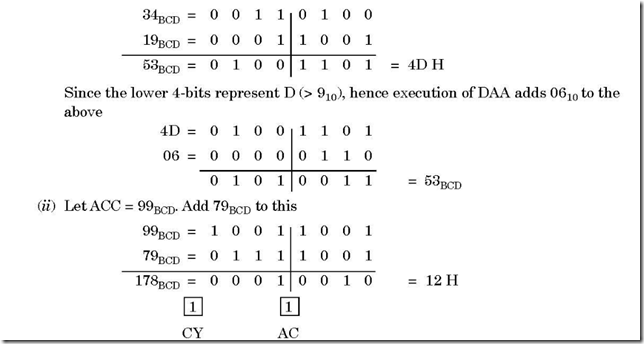
(i) Let ACC contains 34BCD. Add 19BCD to this

10-22-2014 4-45-14 PM


Here both higher order (0001) and lower order (0010) 4-bits are less than 910, but both AC and CY flags are set. Thus, DAA instruction execution will add 6610 to the result.

12 =

0

0

0

1

0

0

1

0

66 =

0

1

1

0

0

1

1

0

0

1

1

1

1

0

0

0

= 78BCD

and since CY is already set, thus the answer is 178BCD.

2. What happens when HLT is executed in software?

Ans. All the buses go into the tri-state on execution of HLT instruction.

3. Write down the instructions that load H-L register pair by the contents of memory location 3500 H. Then move the contents to register C.

Ans. The corresponding instructions are

LXI H, 3500 H          execution of this instruction loads H-L register pair with the contents of memory location 3500 H.

and  MOV C, M        execution of this instruction moves the contents of memory location 3500 H to register C.

4. Explain the two instructions (a) LDAX and (b) STAX

Ans. (a) The instruction LDAX indicates that the contents of the designated register pair point to a memory location and copies the contents of the memory location into the accumulator.

As an example, let D = 40 H, E = 50 H and memory location 4050 H = AB H. Then LDAX D transfers the contents of memory location 4050 H to the accumulator. Thus, after the execution of instruction, ACC = AB H


10-22-2014 4-46-48 PM

(b) STAX stands for ‘store accumulator indirect’. The contents of the accumulator are copied into the memory location specified by the contents of the register pair.

As an example, let D = 40 H and E = 50 H and ACC = AB H. Then STAX D stores the accumulator contents in the memory location 4050 H.


10-22-2014 4-47-28 PM


5. Explain the instructions (a) SHLD (b) LHLD.

4050 = AB H

Ans. (a) It stands for ‘Store H and L registers direct’. The instruction SHLD is followed by a 2-byte address. The content of L is stored in this address and the content of H is stored in the memory location that follows.

As an example, let H = 40 H and L = 50 H. Then execution of SHLD 6555 H stores 50 H in memory location 6555 H and 40 H is stored in 6556 H memory address.


10-22-2014 4-47-45 PM


(b) It stands for ‘Load H and L registers direct’.

It copies the contents of the memory location (that follows an LHLD instruction) into

L register and copies the contents of the next memory location in H register. The

contents of the two accessed memory locations remain unaltered.

As an example, let the memory location 3100 H and 3101 H contain 07 H and AF H

respectively. Then execution of LHLD 3100 H copies the content of 3100 H into L

and that of 3101 H into H register.

10-22-2014 4-47-58 PM


6. Memory location 3050 H is specified by HL pair and contains data FE H. Accumulator contains 14 H. Add the contents of memory location with accumulator. Store the result in 2050 H.

Ans. The program is written as follows:

LXIH, 3050 H fi HL register pair points 3050 H memory location

ADD M fi Add contents of 3050 H with accumulator

STA 2050 H fi Result in accumulator is stored in 2050 H

Prior to execution of the program, memory location 3050 H is loaded with data

FE H and accumulator with 14 H.

7. What the instruction DCR M stands for?

Ans. Here the memory location M is pointed to by the content of HL register pair. On executing DCR M, the content of the memory location is decremented by 01. Thus, if the memory location, as pointed to by HL register pair is AB H, then DCR M makes the content of that memory location to be AA H.

8. What the instruction DAD H stands for?

Ans. On executing the DAD H, the content of HL register pair is multiplied by 2. As an example if


10-22-2014 4-48-18 PM

9. Explain the two instructions (a) RAR and (b) RRC. Ans. (a) RAR stands for ‘rotate accumulator right through carry’.

Let the accumulator content = 95 H and carry flag = 0. Then execution of RAR will

change the contents of CY flag and accumulator as follows:


10-22-2014 4-48-31 PM

Bit D0 is placed in CY flag and the bit in the CY flag is placed in D7.

(b) RRC stands for ‘rotate accumulator right’.

Let, accumulator content = 95 H and carry flag = 0. Then execution of RRC will change the contents of CY flag and accumulator as follows:

10-22-2014 4-48-42 PM


Bit D0 is placed in D7 as well as in CY flag.

10. Explain the two instructions (a) RAL (b) RLC.

Ans. (a) RAL stands for ‘rotate accumulator left through carry’.

Let accumulator content = 95 H and carry flag = 0. Then execution of RAL will change the contents of CY flag and accumulator as follows:

10-22-2014 4-48-54 PM

Here D7 is placed in CY flag and the bit in CY flag placed in D0

(b) RLC stands for ‘rotate accumulator left’.

Let accumulator content = 95 H and carry flag = 0. Then execution of RLC will change the contents of CY flag and accumulator as follows:

10-22-2014 4-49-07 PM


11. Explain the instruction SPHL.

Ans. It stands for ‘Copy H and L registers to the stack pointer’.

This instruction copies the contents of H and L registers into the stack pointer register. The content of H register goes to the high order address and the content of L register to the low order address of SP. H and L register contents remain unchanged.

Let H = 31 H and L = 32 H before the instruction is executed. Hence after its execution, it would be like as follows:


10-22-2014 4-49-20 PM

12. Explain the instruction PCHL.

Ans. It stands for ‘load program counter (PC) with HL contents’. The contents of H and L are copied into higher and lower order bytes of the PC. H and L register contents remain unchanged.

Let H = 31 H and L = 32 H before the instruction is executed. Hence after its execution, it would be as follows:


10-22-2014 4-49-32 PM

13. Write down the result of EX–OR operation on accumulator and register B. Assume ACC = 18 H and B = 27 H.

Ans. The instruction used for this operation is XRA B.

ACC

=

0

0

0

1

1

0

0

0

B

=

0

0

1

0

0

1

1

1

EX–OR

=

0 0

3F H

1

1

1

1

1

1

The result 3F H of EX–OR is stored in accumulator.

14. Consider the following:

Contents of H, L and SP registers are A0 H, B2 H and 3062 H. Memory locations 3062 H and 3063 H contain 52 H and 16 H respectively. Indicate the contents of these registers after XTHL operation.

Ans. XTHL stands for exchange H and L with top of stack.

Different Register contents before XTHL instruction

10-22-2014 4-50-01 PM


After XTHL instruction is carried out, the different register contents would be


10-22-2014 4-50-10 PM


15. Bring out the difference between arithmetic shift and logical shift.

Ans. An example, with a right shift, will be considered to bring out the difference between arithmetic shift and logical shift operations.

Let the accumulator content is


10-22-2014 4-50-28 PM

Then arithmetic right shift operation will make the contents of ACC as follows:


10-22-2014 4-50-40 PM

i.e., the sign bit of the original number is retained at the MSB place.

While logical right shift operation makes the ACC contents as follows:


10-22-2014 4-50-48 PM

i.e., the bits are shifted one bit position to the right.

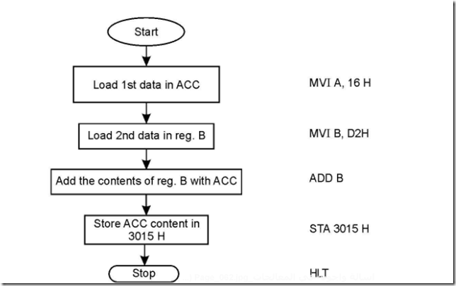
16. Draw the flow chart and write down the program to add two numbers 16 H and D2 H. Store the result in memory location 3015 H.

Ans. The flowchart for the above would look as follows.


10-22-2014 4-51-05 PM


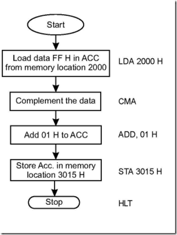
17. Write a program, along with flowchart, to find the 2’s complement of the number FF H, stored at memory location 2000 H. Store the result in memory location 3015 H.

Ans. The flowchart, along with the program, is shown below:

10-22-2014 4-51-22 PM

Memory location 2000 H contains data FF H.

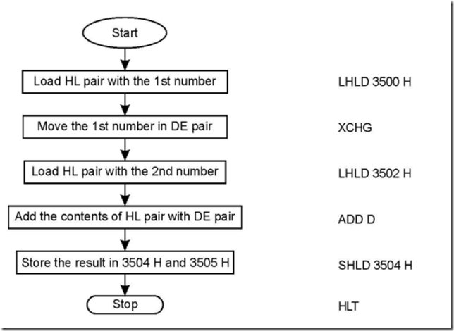
18. Write down the program to add two sixteen bit numbers. Draw the corresponding flowchart also.

Ans. Let the two sixteen bit numbers are stored at memory locations 3500 H to 3503 H. The result of addition is to be stored at memory locations 3504 H and 3505 H. The flowchart and the program will look like as follow:

10-22-2014 4-51-34 PM

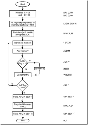
19. Ten 8-bit numbers are stored starting from memory location 2100 H. Add the numbers, store the result at 3500 H memory location and carry at 3501 H. Draw the flowchart also.

Ans. Initially, C register is stored with 09 H to take care of ten 8-bit data. Register D is initialised to 00 and stores the subsequent carry as addition is carried on. Final sum is stored at 3500 H while carry is stored at 3501 H.

10-22-2014 4-51-56 PM

The corresponding flowchart is also shown. Ten numbers of 8-bit data are stored starting from memory location 2100 H.

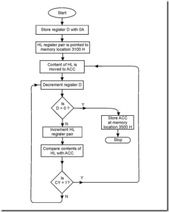
20. Ten 8-bit numbers are stored starting from memory location 3100 H. Find the greatest of the ten numbers and store it at memory location 3500 H.

Ans. Initially, D register is stored with 0A H—the number of data to be compared. The flowchart and the corresponding program are shown below:

10-22-2014 4-52-18 PM


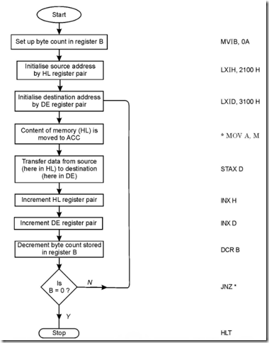
21. Ten number 8-bit data are stored starting from memory location 2100 H. Transfer this entire block of data to memory location starting from 3100 H.

Ans. B register is used here as a counter which stores the number of data bytes to be transferred. The flowchart along with the program are shown below:


10-22-2014 4-52-38 PM

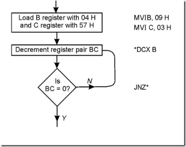
22. Set up a delay of 10 ms. Assume 3 MHz to be the microprocessor clock frequency.

Ans. Time delay is very easily generated by using a register (or a register pair— depending on the delay amount). Here the register pair BC is used to generate the delay with B loaded with 09 H and C with 03 H (calculations shown later). The flowchart and the program are shown side by side.

10-22-2014 4-52-50 PM

Calculations: A 3 MHz system clock corresponds to a time period of 0.3 ms. The

instructions MVI B, MVI C, DCX B and JNZ take 7, 7, 6 and 7 T-states respectively, of

which the two MVI instructions are outside the loop.

Time to execute MVI B and MVI C instructions.

= (7 + 7) × 0.3 ms

If the program loops n times, then time required for n loops

= time for 1 l.oop × n

= (6 + 7) × 0.3 × n

Thus 10 × 103 = (7 + 7) × 0.3 + (6 + 7) × 0.3 × n; fi n ª 2307)10 = 0903)H

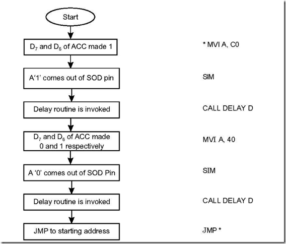
23. Generate a square wave of 50% duty cycle through the SOD pin of 8085. Ans. To generate a square wave, help of SIM instruction is taken. It reads like this


10-22-2014 4-53-06 PM

Thus, for a ‘1’ to come out of SOD pin, D7 and D6 of accumulator to be made 1 while for a ‘0’ to be taken out of SOD pin, D7 and D6 of accumulator to be made 0 and 1 respectively. In both the above cases, D5 to D0 (six bits in all) are to be put to 0. Thus the program reads like this:

10-22-2014 4-53-22 PM

Thus the above generates a square wave which is obtained through SOD pin of microprocessor, having time period of 2D (2 × delay time).

If a non 50% duty cycle is desired, then the two delays are made different, as desired.

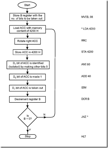
24. A data byte is stored in memory location 4200 H. This eight bit data is to be taken out of SOD pin, bit wise.

Ans. The flowchart and the program are as follows:

10-22-2014 4-53-43 PM


8085 Interrupts

clip_image001

8085 Interrupts

1. Mention the interrupt pins of 8085.

Ans. There are five (5) interrupt pins of 8085—from pin 6 to pin 10. They represent TRAP, RST 7.5, RST 6.5, RST 5.5 and INTR interrupts respectively. These five interrupts are ‘hardware’ interrupts.

2. Explain maskable and non-maskable interrupts.

Ans. An interrupt which can be disabled by software means, is called a maskable interrupt.

Thus an interrupt which cannot be masked is an unmaskable interrupt.

3. Which is the non maskable interrupt for 8085?

Ans. TRAP interrupt is the non-maskable interrupt for 8085. It means that if an interrupt comes via TRAP, 8085 will have to recognise the interrupt.

4. Do the interrupts of 8085 have priority?

Ans. Yes, the interrupts of 8085 have their priorities fixed—TRAP interrupt has the highest priority, followed by RST 7.5, RST 6.5, RST 5.5 and lastly INTR.

5. What is meant by priority of interrupts?

Ans. It means that if 8085 is interrupted by more than one interrupt at the same time, the one which is having highest priority will be serviced first, followed by the one(s) which is (are) having just next priority and so on.

For example, if 8085 is interrupted by RST 7.5, INTR and RST 5.5 at the same time,

then the sequence in which the interrupts are going to be serviced are as follows: RST

7.5, RST 5.5 and INTR respectively.

6. Mention the types of interrupts that

8085 supports.

Ans. 8085 supports two types of interrupts— hardware and software interrupts.

7. What are the software interrupts of 8085? Mention the instructions, their hex codes and the corresponding vector addresses.

Ans. 8085 has eight (8) software interrupts from RST 0 to RST 7. The instructions, hex codes and the vector locations are tabulated in Table 4.1:

Table 4.1: Vector addresses for software interrupts

Instruction

Corresponding HEX code

Vector addresses

RST 0

C7

0000H

RST 1

CF

0008H

RST 2

D7

0010H

RST 3

DF

0018H

RST 4

E7

0020H

RST 5

EF

0028H

RST 6

F7

0030H

RST 7

FF

0038H

8. How the vector address for a software interrupt is determined?

Ans. The vector address for a software interrupt is calculated as follows:

Vector address = interrupt number × 8

For example, the vector address for RST 5 is calculated as

5 × 8 = 40)10 = 28)H

Vector address for RST 5 is 0028H.

9. In what way INTR is different from the other four hardware interrupts? Ans. There are two differences, which are discussed below:

1. While INTR is not a vectored interrupt, the other four, viz., TRAP, RST 7.5, RST

6.5 and RST 5.5 are all vectored interrupts. Thus whenever an interrupt comes via any one of these four interrupts, the internal control circuit of 8085 produces a CALL to a predetermined vector location. At these vector locations the subroutines are written.

On the other hand, INTR receives the address of the subroutine from the external

device itself.

2. Whenever an interrupt occurs via TRAP, RST 7.5, RST 6.5 or RST 5.5, the corresponding returns address (existing in program counter) is auto-saved in STACK, but this is not so in case of INTR interrupt.

10. Indicate the nature of signals that will trigger TRAP, RST 7.5, RST 6.5, RST 5.5 and INTR.

Ans. TRAP interrupt is both positive edge and level triggered, RST 7.5 is positive edge triggered while RST 6.5, RST 5.5 and INTR are all level triggered.

11. Why the TRAP input is edge and level sensitive?

Ans. TRAP input is edge and level sensitive to avoid false triggering caused by noise and transients.

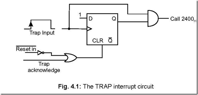
12. Draw the TRAP interrupt circuit diagram and explain the same.

Ans.

10-22-2014 4-20-30 PM


The positive edge of the TRAP signal sets the D F/F, so that Q becomes 1. It thus enables the AND gate, but the AND gate will output a 1 for a sustained high level at the TRAP input. In that case the subroutine written at vector memory location 2400H corresponding to TRAP interrupt starts executing. 2400H is the starting address of an interrupt service routine for TRAP.

There are two ways to clear the TRAP interrupt:

1. When the microprocessor is resetted, then via the inverter, a high comes out of the OR gate, thereby clearing the D F/F, making Q = 0.

2. When a TRAP is acknowledged by the system, an internal TRAP ACKNOWLEDGE is generated thereby clearing the D F/F.

13. Discuss the INTR interrupt of 8085.

Ans. The following are the characteristics of INTR interrupt of 8085:

*It is a maskable interrupt

* It has lowest priority

* It is a non-vectored interrupt.

Sequentially, the following occurs when INTR signal goes high:

1. 8085 checks the status of INTR signal during execution of each instruction.

2. If INTR signal remains high till the completion of an instruction, then 8085 sends

out an active low interrupt acknowledge (INTA) signal.

3. When INTA signal goes low, external logic places an instruction OPCODE on the

data bus.

4. On receiving the instruction, 8085 saves the address of next instruction (which would have otherwise been executed) in the STACK and starts executing the ISS (interrupt service subroutine).

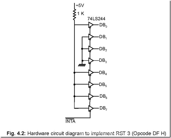
14. Draw the diagram that outputs RST 3 instruction opcode on acknowledging the interrupt.

Ans. The diagram is shown below:


10-22-2014 4-20-55 PM

When an INTR is acknowledged by the microprocessor, it outputs a low INTA . Thus

an RST 3 is gated onto the system bus. The processor then first saves the PC in the STACK and branches to the location 0018H. At this address, the ISS begins and ends with a RET instruction. On encountering RET instruction in the last line of the ISS, the return address saved in the stack is restored in the PC so that normal processing in the main program (at the address which was left off when the program branched to ISS) begins.

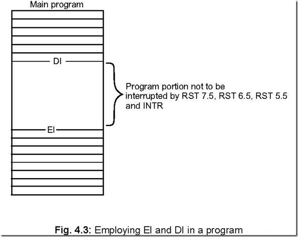
15. What is to be done if a particular part of a program is not to be interrupted by RST 7.5, RST 6.5, RST 5.5 and INTR?

Ans. Two software instructions—EI and DI are used at the beginning and end of the particular portion of the program respectively. The scheme is shown schematically as follows:


10-22-2014 4-21-33 PM

16. Explain the software instructions EI and DI.

Ans. The EI instruction sets the interrupt enable flip-flop, thereby enabling RST 7.5, RST 6.5, RST 5.5 and INTR interrupts.

The DI instruction resets the interrupt enable flip-flop, thereby disabling RST 7.5, RST 6.5, RST 5.5 and INTR interrupts.

17. When returning back to the main program from Interrupt Service Subroutine (ISS), the software instruction EI is inserted at the end of the ISS. Why?

Ans. When an interrupt (either via RST 7.5, RST 6.5, RST 5.5, INTR) is acknowledged by the microprocessor, ‘any interrupt acknowledge’ signal resets the interrupt enable F/F. It thus disables RST 7.5, RST 6.5, RST 5.5 and INTR interrupts. Thus any future interrupt coming via RST 7.5, RST 6.5, RST 5.5 or INTR will not be acknowledged unless the software instruction EI is inserted which thereby sets the interrupt enable F/F.

18. Mention the ways in which the three interrupts RST 7.5, RST 6.5 and RST 5.5 are disabled?

Ans. The three interrupts can be disabled in the following manner:

*Software instruction DI

* RESET IN signal

*Any interrupt acknowledge signal.

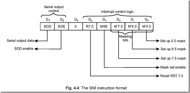
19. Draw the SIM instruction format and discuss.

Ans. The SIM instruction format is shown below:


10-22-2014 4-22-28 PM

D7 and D6 bits are utilised for serial outputting of data from accumulator. D5 bit is a don’t care bit, while bits D4–D0 are used for interrupt control.

D4 bit can clear the D F/F associated with RST 7.5.

D3 bit is mask set enable (MSE) bit, while bits D2–D0 are the masking bits

corresponding to RST 7.5, RST 6.5 and RST 5.5 respectively.

None of the flags are affected by SIM instruction.

By employing SIM instruction, the three interrupts RST 7.5, RST 6.5 and RST 5.5 can be masked or unmasked. For masking any one of these three interrupts, MSE (i.e., bit D3) bit must be 1.

For example let RST 7.5 is to be masked (disabled), while RST 6.5 and RST 5.5 are

to be unmasked (enabled), then the content of the bits of the SIM instruction will be like 0000 1100 = 0CH

For this to be effective the following two instructions are written,

MVI A, 0CH SIM

Execution of SIM instruction allows copying of the contents of the accumulator into

the interrupt masks.

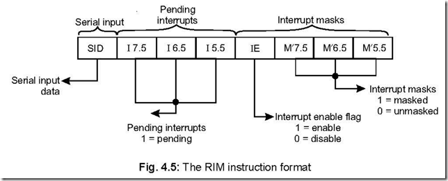
20. Show the RIM instruction format and discuss the same. Ans. RIM stands for ‘Read interrupt mask’ and its format is as follows:

10-22-2014 4-23-25 PM

When RIM instruction is executed in software, the status of SID, pending interrupts and interrupt masks are loaded into the accumulator. Thus their status can be monitored. It may so happen that when one interrupt is being serviced, other interrupt(s) may occur. The status of these pending interrupts can be monitored by the RIM instruction. None of the flags are affected by RIM instruction.

21. Write a program which will call the interrupt service subroutine (at 3C00H) corresponding to RST 7.5 if it is pending. Let the ACC content is 20 H on executing the RIM instruction.

Ans. The program for the above will be as hereunder:


10-22-2014 4-23-53 PM

22. Write a program which will call the subroutine (say named ‘SR’) if RST 6.5 is masked. Let content of ACC is 20 H on executing the RIM instruction.

Ans. RST 6.5 is masked if bit M¢6.5 (D1 bit of RIM) is a 1 and also D3 bit (i.e., IE) is 1 The program for the above will be as hereunder:


10-22-2014 4-24-20 PM

23. For what purpose TRAP interrupt is normally used?

Ans. TRAP interrupt is a non-maskable one i.e., if an interrupt comes via the TRAP input, the system will have to acknowledge that. That is why it is used for vital purposes which require immediate attention like power failure.

If the microprocessor based system loses power, the filter capacitors hold the supply voltage for several mili seconds.

During this time, data in the RAM can be written in a disk or E2PROM for future

usage.

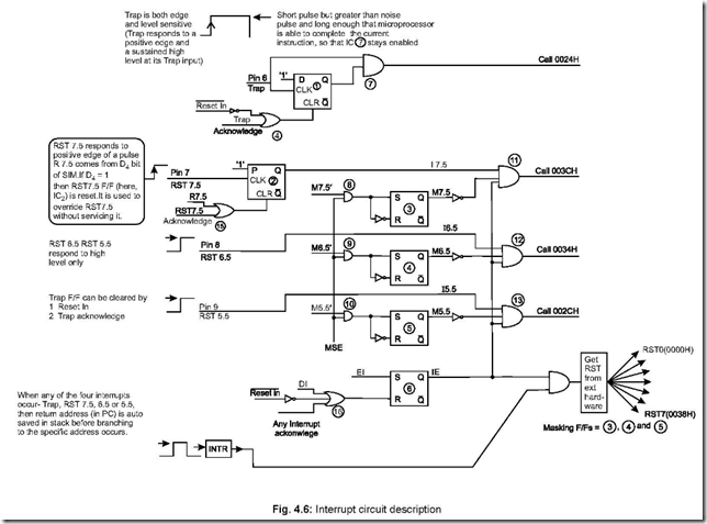
24. Draw the interrupt circuit diagram for 8085 and explain.

Ans. Figure 4.6 is the interrupt circuit diagram of 8085. It shows the five hardware interrupts TRAP, RST 7.5, RST 6.5, RST 5.5 and INTR along with the software interrupts RST n: n = 0 to 7.

Trap is both edge and level sensitive interrupt. A short pulse should be applied at the

trap input, but the pulse width must be greater than a normal noise pulse width and also long enough for the µP to complete its current instruction. The trap input must come down to low level for it to be recognised for the second time by the system. It is having highest priority.

Next highest priority interrupt is RST 7.5 which responds to the positive edge

(low to high transition) of a pulse. Like trap, it also has a D F/F whose output becomes 1 on accepting the RST 7.5 input, but final call to vector location 3C00H is reached only if RST 7.5 remains unmasked and the program has an EI instruction inserted already. These are evident from the circuit. If R 7.5 (bit D4 of SIM instruction) is 1, then RST 7.5 instruction will be overlooked i.e., it can override any RST 7.5 interrupt.

Like RST 7.5, final call locations 3400H and 2C00H corresponding to interrupts at RST 6.5 and RST 5.5 are reached only if the two interrupts remain unmasked and the software instruction EI is inserted.

The three interrupts RST 7.5, RST 6.5 and RST 5.5 are disabled once the system accepts an interrupt input via any one of these pins—this is because of the generation of ‘any interrupt acknowledge’ signal which disables them.

Any of the software RST instructions (RST n : n = 0 to 7) can be utilised by using

INTR instruction and hardware logic. RST instructions are utilised in breakpoint service routine to check register(s) or memory contents at any point in the program.

25. The process of interrupt is asynchronous in nature. Why?

Ans. Interrupts may come and be acknowledged (provided masking of any interrupt is not done) by the microprocessor without any reference to the system clock. That is why interrupts are asynchronous in nature.

26. In how many categories can ‘interrupt requests’ be classified?

Ans. The ‘interrupt requests’ can be classified into two categories—maskable interrupt and non-maskable interrupt.

A maskable interrupt can either be ignored or delayed as per the needs of the system

while a non-maskable interrupt has to be acknowledged.


10-22-2014 4-24-57 PM27. When the interrupt pins of 8085 are checked by the system?

Ans. Microprocessor checks (samples) interrupt pins one cycle before the completion of an instruction cycle, on the falling edge of the clock pulse. An interrupt occurring at least 160 ns (150 ns for 8085A-2, since it is faster in operation) before the sampling time is treated as a valid interrupt.

28. Is there a minimum pulse width required for the INTR signal?

clip_image028Ans. Microprocessor issues a low INTA signal as an acknowledgement on receiving an INTR interrupt input signal. A CALL instruction is then issued so that the program branches to Interrupt Service Subroutine (ISS). Now the CALL requires 18 T-states to complete. Hence the INTR pulse must remain high for at least 17.5 T-states. If 8085 is operated at 3 MHz clock frequency, then the INTR pulse must remain high for at least 5.8 mS.

29. Can the microprocessor be interrupted before completion of existing Interrupt Service Subroutine (ISS)?

Ans. Yes, the microprocessor can be interrupted before the completion of the existing ISS.

Let after acknowledging the INTR, the microprocessor is in the ISS executing instructions one by one. Now, for a given situation, if the interrupt system is enabled (by inserting an EI instruction) just after entering the ISS, the system can be interrupted again while it is in the first ISS.

If an interrupt service subroutine be interrupted again then this is called ‘nested interrupt’.

30. Bring out one basic difference between SIM and DI instructions.

Ans. While by using SIM instruction any combinations or all of RST 7.5, RST 6.5 and RST 5.5 can be disabled, on the other hand DI disables RST 7.5, RST 6.5, RST 5.5 and in addition INTR interrupt also.

31. What is RIM instruction and what does it do?

Ans. The instruction RIM stands for Read Interrupt Mask. By executing this instruction in software, it is possible to know the status of interrupt mask, pending interrupt(s), and serial input.

32. In an interrupt driven system, EI instruction should be incorporated at the beginning of the program. Why?

Ans. A program, written by a programmer in the RAM location, is started first by system reset and loading the PC with the starting address of the program.

Now, with a system reset, all maskable interrupts are disabled. Hence, an EI

instruction must be put in at the beginning of the program so that the maskable interrupts, which should remain unmasked in a program, remain so.

33. How the system can handle multiple interrupts?

Ans. Multiple interrupts can be handled if a separate interrupt is allocated to each peripheral.

The programmable interrupt controller IC 8259 can also be used to handle multiple interrupts when they are interfaced through INTR.

34. When an interrupt is acknowledged, maskable interrupts are automatically disabled. Why?

Ans. This is done so that the interrupt service subroutine (ISS) to which the program has entered on receiving the interrupt, has a chance to complete its own task.

35. What is meant by ‘nested interrupts’? What care must be taken while handling nested interrupts?

Ans. Interrupts occurring within interrupts are called ‘nested interrupts’.

While handling nested interrupts, care must be taken to see that the stack does not grow to such an extent as to foul the main program—in that case the system program fails.

36. A RIM instruction should be performed immediately after TRAP occurs’—Why?

Ans. This is so as to enable the pre-TRAP interrupt status to be restored with the implementation of a SIM instruction.

37. What does the D4 bit of SIM do?

Ans. Bit D4 of SIM is R 7.5 which is connected to RST 7.5 F/F via a OR gate. If D4 of SIM is made a 1, then it resets RST 7.5 F/F. This thus can be used to override RST 7.5 without servicing it.

38. Comment on the TRAP input of 8085.

Ans. Trap input is both edge and level sensitive. It is a narrow pulse, but the pulse width should be more than normal noise pulse width. This is done so that noise cannot affect the TRAP input with a false triggering. Again the pulse width should be such that the TRAP input which is directly connected to the gate stays high till the completion of current instruction by the mP. In that case, only the program gets diverted to vector call location 2400 H.

TRAP cannot respond for a second time until the first TRAP goes through a high to low transition.

TRAP interrupt, once acknowledged, goes to 2400 H vector location without any external hardware or EI instruction, as is the case for other interrupt signals to be acknowledged.

39. Discuss about the triggering levels of RST 7.5, RST 6.5 and RST 5.5.

Ans. RST 7.5 is positive edge sensitive and responds to a short trigger pulse. The interrupt that comes via RST 7.5 is stored in a D F/F, internal to mP. The final vector call location 3C00 H is invoked only if RST 7.5 remains unmasked via SIM and software instruction EI is inserted in the program.

RST 6.5 and 5.5 respond to high level (i.e., level sensitive) at their input pins—thus these two pins must remain high until microprocessor completes the execution of the current instruction.

40. Discuss the utility of RST software instruction.

Ans. For an RST instruction (RST n, n : 0 to 7) to become effective, external hardware is necessary, along with INTR interrupt instruction.

When debugging is required in a program to know the register(s) or memory contents, breakpoints are inserted via RST instruction.

A breakpoint is an RST instruction inserted in a program. When an RST instruction is recognised, the program control is transferred to the corresponding RST vector location. From this vector location, it is again transferred to the breakpoint service routine so that programmer can check the contents of any register or memory content on pressing specified key(s). After testing, the routine returns to the breakpoint in the main program.

Thus RST instructions can be inserted within a program to examine the register/

memory content as per the requirement.

41. Under what condition, an RST instruction is going to be recognised?

Ans. Any RST instruction is recognised only if the EI instruction is incorporated via software.

42. Can the ‘TRAP’ interrupt be disabled by a combination of hardware and software?

Ans. Yes, it can be disabled by SIM instruction and hardware, as shown in Fig. 4.7.

The following two instructions are executed.

MVIA, 40 H

SIM

It ensures that a ‘0’ logic comes out via SOD pin (pin 4) of 8085. This is then ANDed with TRAP input.


10-22-2014 4-25-23 PM

Thus pin 6 (TRAP) always remains at ‘0’ logic and hence TRAP input is disabled or ‘MASKED’.

43. Level wise, how the interrupts can be classified? Distinguish them.

Ans. Level wise, interrupts can be classified as

1 single level interrupts

2 multi level interrupts

Their distinguishing features are shown below:

Single level interrupt

Multi level interrupt

1. Interrupts are fed via a single pin

of microprocessor (like INTR of 8085)

2. CPU polls the I/O devices to identify the interrupting device.

3. Slower because of sl. no. 2.

1. Interrupts are fed via different pins of microprocessor (like RST 7.5, RST 6.5 etc), each interrupt requiring a separate pin of microprocessor.

2. Since each interrupt pin corresponds to a single I/O device, polling is not necessary.

3. Faster because of sl. no. 2.


Instruction Types and Timing Diagrams

Instruction Types and Timing Diagrams

1. What is an instruction?

Ans. An instruction is a command given to the microcomputer to perform a specific task or function on a given data.

2. What is meant by instruction set?

Ans. An instruction set is a collection of instructions that the microprocessor is designed to perform.

3. In how many categories the instructions of 8085 be classified? Ans. Functionally, the instructions can be classified into five groups:

*data transfer (copy) group

*arithmetic group

*logical group

* branch group

*stack, I/O and machine control group.

4. What are the different types of data transfer operations possible? Ans. The different types of data transfer operations possible are cited below:

* Between two registers.

* Between a register and a memory location.

*A data byte can be transferred between a register and a memory location.

* Between an I/O device and the accumulator.

*Between a register pair and the stack.

The term ‘data transfer’ is a misnomer—actually data is not transferred, but copied from source to destination.

5. Mention the different types of operations possible with arithmetic, logical, branch and machine control operations.

Ans. The arithmetic operations possible are addition, subtraction, increment and decrement.

The logical operations include AND, OR, EXOR, compare, complement, while branch

operations are Jump, Call, Return and Restart instructions.

The machine control operations are Halt, Interrupt and NOP (no operation).

6. What are the different instruction word sizes in 8085? Ans. The instruction word sizes are of the following types:

Instruction Types and Timing Diagrams 33

z 1-byte instruction z 2-byte instruction z 3-byte instruction.

7. What an instruction essentially consists of?

Ans. An instruction comprises of an operation code (called ‘opcode’) and the address of the data (called ‘operand’), on which the opcode operates. This is the structure on which an instruction is based. The opcode specifies the nature of the task to be performed by an instruction. Symbolically, an instruction looks like

10-22-2014 4-03-18 PM

8. Give one example each of 1-byte, 2-byte and 3-byte instructions.

Ans. The examples are given below:

* 1-byte instruction : ADD B

* 2-byte instruction : MVIC, 07

* 3-byte instruction : LDA 4400


10-22-2014 4-04-38 PM


9. What is meant by ‘addressing mode’? Mention the different addressing modes.

Ans. Each instruction indicates an operation to be performed on certain data. There are various methods to specify the data for the instructions, known as ‘addressing modes’.

For 8085 microprocessor, there are five addressing modes. These are:

*Direct addressing

* Register addressing

* Register indirect addressing

* Immediate addressing

*Implicit addressing.

10. Give one example each of the five types of addressing modes. Ans. The examples for each type of addressing mode are given below:

(a) Direct Addressing: In this mode, the operand is specified within the instruction itself.

Examples of this type are:

LDA 4000H, STA 5513H, etc.

IN/OUT instructions (like IN PORT C, OUT PORT B, etc.) also falls under this category.

(b) Register Addressing: In this mode of addressing, the operand are in the general purpose registers.

Examples are: MOV A, B ; ADD D, etc.

(c) Register Indirect Addressing: MOV A, M; ADD M are examples of this mode of addressing. These instructions utilise 1-byte. In this mode, instead of specifying a register, a register pair is specified to accommodate the 16-bit address of the operand.

(d) Immediate Addressing: MVI A, 07; ADI 0F are examples of Immediate Addressing mode.

The operand is specified in the instruction in this mode. Here, the operand address is not specified.

(e) Implicit Addressing: In this mode of addressing, the operand is fully absent. Examples are RAR, RAL, CMA, etc.

11. Let at the program memory location 4080, the instruction MOV B, A (opcode 47H) is stored while the accumulator content is FFH. Illustrate the execution of this instruction by timing diagram.

Ans. Since the program counter sequences the execution of instructions, it is assumed that

the PC holds the address 4080H. While the system one after another.

1. The CPU places the address 4080H (residing in PC) on the address bus—40H on the high

CLK A 1 T2 T3 T4 order bus A15 – A8 and 80H on the low order bus AD7 – AD0.

2. The CPU raises the ALE signal to go high—the H to L transition of ALE at the end of the

first T state demultiplexes the low order bus.

3. The CPU identifies the nature of the machine cycle by means of the three status IO/M

signals IO/ M , S0 and S1.

IO/ = 0, S1 = 1, S0 = 1

4. In T2, memory is enabled by the signal.

The content of PC i.e., 47H is placed on the data bus. PC is incremented to 4081H.

5. In T3, CPU reads 47H and places it in the instruction register.

10-22-2014 4-05-15 PM

6. In T4, CPU decodes the instruction, places FFH (accumulator content) in the temporary register and then transfers it to register B. Figure 3.1 shows the execution of the above. It consists of 4T states.


The 8085 Microprocessor

The 8085 Microprocessor

1. Draw the pin configuration and functional pin diagram of μP 8085. Ans. The pin configuration and functional pin diagram of μP 8085 are shown below:
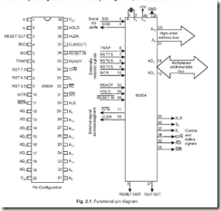
 

10-21-2014 8-01-42 PM


2. In how many groups can the signals of 8085 be classified?

Ans. The signals of 8085 can be classified into seven groups according to their functions. These are:

(1) Power supply and frequency signals (2) Data and Address buses (3) Control bus

(4) Interrupt signals (5) Serial I/O signals (6) DMA signals (7) Reset signals.

3. Draw the architecture of 8085 and mention its various functional blocks. Ans. The architecture of 8085 is shown below:
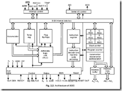
 

10-21-2014 8-22-48 PM


Fig. 2.2: Architecture of 8085

The various functional blocks of 8085 are as follows:

1.Registers

2.Arithmetic logic unit

3.Address buffer

4.Incrementer/decrementer address latch

5.Interrupt control

6. Serial I/O control

7.Timing and control circuitry

8.Instructions decoder and machine cycle encoder.

4. What is the technology used in the manufacture of 8085?

Ans. It is an NMOS device having around 6200 transistors contained in a 40 pin DIP package.

5. What is meant by the statement that 8085 is a 8-bit microprocessor?

Ans. A microprocessor which has n data lines is called an n-bit microprocessor i.e., the width of the data bus determines the size of the microprocessor. Hence, an 8-bit microprocessor like 8085 can handle 8-bits of data at a time.

6. What is the operating frequency of 8085?

Ans. 8085 operates at a frequency of 3 MHz, and the minimum frequency of operation is 500 kHz.

The version 8085 A-2 operates at a maximum frequency of 5 MHz.

7. Draw the block diagram of the built-in clock generator of 8085.

Ans. The built-in clock generator of 8085, in block schematic, is shown below:


10-21-2014 8-23-09 PM


The internal built-in clock generator, LC or RC tuned circuits, piezo-electric crystal or external clock source acts as an input to generate the clock. The T F/F, shown in Fig.

2.3 divides the input frequency by 2. Thus the output frequency of 8085 (obtained from pin 37) is half the input frequency.

8. What is the purpose of CLK signal of 8085?

Ans. The CLK (out) signal obtained from pin 37 of 8085 is used for synchronizing external devices.

9. Draw the different clock circuits which can be connected to pins 1 and 2 of 8085.

Ans. The different external clock circuits which can be connected to pins 1 and 2 of 8085 are shown below in Fig. 2.4:

10-21-2014 8-23-26 PM

Fig. 2.4: The different external clock circuits

The output frequency obtained from pin 37 of Fig. 2.4(b) is more stable than the RC circuit of Fig. 2.4(a).

10. What are the widths of data bus (DB) and address bus (AB) of 8085?

Ans. The width of DB and AB of 8085 are 8-bits (1 byte) and 16-bits (2 bytes) respectively.

11. What is the distinguishing feature of DB and AB?

Ans. While the data bus is bidirectional in nature, the address bus is unidirectional.

Since the mP can input or output data from within it, hence DB is bidirectional. Again the microprocessor addresses/communicates with peripheral ICs through the address bus, hence it is unidirectional, the address comes out via the AB of mP.

12. The address capability of 8085 is 64 KB. Explain.

Ans. Microprocessor 8085 communicates via its address bus of 2-bytes width – the lower byte AD0 – AD7 (pins 12-19) and upper byte D8 – D15 (pins 21–28). Thus it can address a maximum of 216 different address locations. Again each address (memory location) can hold 1 byte of data/instruction. Hence the maximum address capability of 8085 is

= 216 × 1 Byte

= 65, 536 × 1 Byte

= 64 KB (where 1 K = 1024 bytes)

13. Does 8085 have serial I/O control?

Ans. 8085 has serial I/O control via its SOD and SID pins (pins 4 and 5) which allows it to communicate serially with external devices.

14. How many instructions 8085 can support? Ans. 8085 supports 74 different instructions.

15. Mention the addressing modes of 8085.

Ans. 8085 has the following addressing modes: Immediate, Register, Direct, Indirect and Implied.

16. What jobs ALU of 8085 can perform?

Ans. The Arithmetic Logic Unit (ALU) of 8085 can perform the following jobs:

1.8-bit binary addition with or without carry.

2.16-bit binary addition.

3. 2-digit BCD addition.

4. 8-bit binary subtraction with or without borrow.

5. 8-bit logical OR, AND, EXOR, complement (NOT function).

6.bit shift operation.

17. How many hardware interrupts 8085 supports?

Ans. It supports five (5) hardware interrupts—TRAP, RST 7.5, RST 6.5, RST 5.5 and INTR.

18. How many I/O ports can 8085 access?

Ans. It provides 8-bit I/O addresses. Thus it can access 28 = 256 I/O ports.

19. Why the lower byte address bus (A0 – A7) and data bus (D0 – D7) are multiplexed? Ans. This is done to reduce the number of pins of 8085, which otherwise would have been a

48 pin chip. But because of multiplexing, external hardware is required to demultiplex

the lower byte address cum data bus.

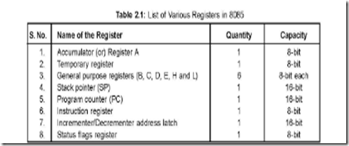
20. List the various registers of 8085.

Ans. The various registers of 8085, their respective quantities and capacities are tabulated below:
10-21-2014 8-23-52 PM

21. Describe the accumulator register of 8085.

Ans. This 8-bit register is the most important one amongst all the registers of 8085. Any data input/output to/from the microprocessor takes place via the accumulator (register). It is generally used for temporary storage of data and for the placement of final result of arithmetic/logical operations.

Accumulator (ACC or A) register is extensively used for arithmetic, logical, store and rotate operations.

22. What are the temporary registers of 8085?

Ans. The temporary registers of 8085 are temporary data register and W and Z registers. These registers are not available to the programmer, but 8085 uses them internally to hold temporary data during execution of some instructions.

23. Describe W and Z registers of 8085.

Ans. W and Z are two 8-bit temporary registers, used to hold 8-bit data/address during execution of some instructions.

CALL-RET instructions are used in subroutine operations. On getting a CALL in the main program, the current program counter content is pushed into the stack and loads the PC with the first memory location of the subroutine. The address of the first memory location of the subroutine is temporarily stored in W and Z registers.

Again, XCHG instruction exchanges the contents H and L with D and E respectively. W and Z registers are used for temporary storage of such data.

24. Describe the temporary data register of 8085.

Ans. The temporary data register of 8085 is an 8-bit register, which is not available to the programmer, but is used internally for execution of most of the arithmetic and logical operations.

ADD D instruction adds the contents of accumulator with the content of D. The content of D is temporarily brought into the temporary data register. Thus the two inputs to the ALU are—one from the accumulator and the other from the temporary data register. The result is stored in the accumulator.

25. Describe the general purpose registers of 8085?

Ans. The general purpose registers of 8085 are: B, C, D, E, H and L. They are all 8-bit registers but can also be used as 16-bit register pairs—BC, DE and HL. These registers are also known as scratch pad registers.

26. In what other way HL pair can be used?

Ans. HL register pair can be used as a data pointer or memory pointer.

27. Mention the utility of the general purpose registers.

Ans. General purpose registers store temporary data during program execution, which can also be stored in different accessible memory locations. But storing temporary data in memory requires bus access—hence more time is needed to store. Thus it is always advisable to store data in general purpose registers.

The more the number of general purpose registers, the more is flexibility in programming—so a microprocessor having more such registers is always advantageous.

28. Which are the sixteen bit registers of 8085.

Ans. 8085 has three (3) sixteen bit registers—Program Counter (PC), Stack Pointer (SP) and Incrementer/Decrementer address latch register.

29. Discuss the two registers program counter and stack pointer.

Ans. Program counter (PC) is a sixteen bit register which contains the address of the instruction to be executed just next. PC acts as a address pointer (also known as memory pointer) to the next instruction. As the processor executes instructions one after another, the PC is incremented—the number by which

the PC increments depends on the nature of the instruction. For example, for a 1-byte instruction, PC is incremented by one, while for a 3-byte instruction, the processor increments PC by three address locations.

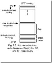
Stack pointer (SP) is a sixteen bit register which points to the ‘stack’. The stack is an area in the R/W memory where temporary data or return addresses (in cases of subroutine CALL) are stored. Stack is a auto- decrement facility provided in the system. The stack top is initialised by the SP by using the instruction LXI SP, memory address.

In the memory map, the program should Fig. 2.5: Auto-increment and be written at one end and stack should be auto-decrement facility for PC initialised at the other end of the map—this is and SP respectively done to avoid crashing of program. If sufficient
10-21-2014 8-24-16 PM

gap is not maintained between program memory location and stack, then when the stack gets filled up by PUSH or subroutine calls, the stack top may run into the memory area where program has been written. This is shown in Fig. 2.5.

30. Describe the instruction register of 8085.

Ans. Program written by the programmer resides in the R/W memory. When an instruction is being executed by the system, the opcode of the instruction is fetched from the memory and stored in the instruction register. The opcode is loaded into the instruction register during opcode fetch cycle. It is then sent to the instruction decoder.

31. Describe the (status) flag register of 8085.

Ans. It is an 8-bit register in which five bit positions contain the status of five condition flags which are Zero (Z), Sign (S), Carry (CY), Parity (P) and Auxiliary carry (AC). Each of these five flags is a 1 bit F/F. The flag register format is shown in Fig. 2.6:

10-21-2014 8-24-32 PM


* Sign (S) flag: – If the MSB of the result of an operation is 1, this flag is set, otherwise it is reset.

* Zero (Z) flag:– If the result of an instruction is zero, this flag is set, otherwise reset.

* Auxiliary Carry (AC ) flag:– If there is a carry out of bit 3 and into bit 4 resulting from the execution of an arithmetic operation, it is set otherwise reset.

This flag is used for BCD operation and is not available to the programmer to change the sequence of an instruction.

* Carry (CY) flag:– If an instruction results in a carry (for addition operation) or borrow (for subtraction or comparison) out of bit D7, then this flag is set, otherwise reset.

* Parity (P) flag:– This flag is set when the result of an operation contains an even number of 1’s and is reset otherwise.

32. State the characteristics of the flag register. Ans. The following are the characteristics of flag register:

z It is an 8-bit register.

z It contains five flags—each of one bit.

z The flag register can’t be written into.

33. What is the purpose of incrementer/decrementer address latch register?

Ans. This 16-bit register increments/decrements the contents of PC or SP when instructions related to them are executed.

34. Mention the blocks on which ALU operates?

Ans. The ALU functions as a part which includes arithmetic logic group of circuits. This includes accumulator, flags F/Fs and temporary register blocks.

35. What is the function of the internal data bus?

Ans. The width of the internal data bus is 8-bit and carries instructions/data between the CPU registers. This is totally separate from the external data bus which is connected to memory chips, I/O, etc.

The internal and external data bus are connected together by a logic called a bidirectional bus (transreceiver).

36. Describe in brief the timing and control circuitry of 8085.

Ans. The T&C section is a part of CPU and generates timing and control signals for execution of instructions. This section includes Clock signals, Control signals, Status signals, DMA signals as also the Reset section. This section controls fetching and decoding operations. It also generates appropriate control signals for instruction execution as also the signals required to interface external devices.

37. Mention the following:

(a) Control and Status signals

(b) Interrupt signals

(c) Serial I/O signals

(d) DMA signals

(e) Reset signals.

Ans. The control and status signals are ALE, RD , WR , IO/M , S0, S1 and READY.

The interrupt signals are TRAP, RST 7.5, RST 6.5, RST 5.5, INTR. INTA is an

interrupt acknowledgement signal indicating that the processor has acknowledged an

INTR interrupt.

Serial I/O signals are SID and SOD

DMA signals are HOLD and HLDA


Reset signals are RESET IN and RESET OUT.

38. What is the function of ALE and how does it function?

Ans. Pin 30 of 8085 is the ALE pin which stands for ‘Address Latch Enable’. ALE signal is used to demultiplex the lower order address bus (AD0 – AD7).

Pins 12 to 19 of 8085 are AD0 – AD7 which is the multiplexed address-data bus. Multiplexing is done to reduce the number of pins of 8085.

Lower byte of address (A0 – A7) are available from AD0 – AD7 (pins 12 to 19) during T1 of machine cycle. But the lower byte of address (A0 – A7), along with the upper byte A8 – A15 (pins 21 to 28) must be available during T2 and rest of the machine cycle to access memory location or I/O ports.

Now ALE signal goes high at the beginning of T1 of each machine cycle and goes low at the end of T1 and remains low during the rest of the machine cycle. This high to low transition of ALE signal at the end of T1 is used to latch the lower order address byte (A0 – A7) by the latch IC 74LS373, so that the lower byte A0 – A7 is continued to be available till the end of the machine cycle. The situation is explained in the following figure:

10-21-2014 8-24-54 PM

Fig. 2.7: Lower byte of address latching achieved by the H to L transition of ALE signal, which occurs at the end of T1 of each machine cycle

39. Explain the function of the two DMA signals HOLD and HLDA.

Ans. DMA mode of data transfer is fastest and pins 39 and 38 (HOLD and HLDA) become active only in this mode.

When DMA is required, the DMA controller IC (8257) sends a 1 to pin 39 of 8085. At the end of the current instruction cycle of the microprocessor it issues a 1 to pin 38 of the controller. After this the bus control is totally taken over by the controller.

When 8085 is active and 8257 is idle, then the former is MASTER and the latter is SLAVE, while the roles of 8085 and 8257 are reversed when 8085 is idle and 8257 becomes active.

40. clip_image020Discuss the three signals IO/ M , S0 and S1.

clip_image021Ans. IO/ M signal indicates whether I/O or memory operation is being carried out. A high on this signal indicates I/O operation while a low indicates memory operation. S0 and S1 indicate the type of machine cycle in progress.

41. What happens when RESET IN signal goes low?

Ans. RESET IN is an input signal which is active when its status is low. When this pin is

low, the following occurs:

z The program counter is set to zero (0000H).

z Interrupt enable and HLDA F/Fs are resetted.

z All the buses are tri-stated.

z Internal registers of 8085 are affected in a random manner.

42. Is there any minimum time required for the effective RESET IN signal?

Ans. For proper resetting to take place, the reset signal RESET IN must be held low for at

least 3 clock cycles.

43. Indicate the function of RESET OUT signal.

Ans. When this signal is high, the processor is being reset. This signal is synchronised to the processor clock and is used to reset other devices which need resetting.

44. Write the advantages/disadvantages of having more number of general purpose registers in a microprocessor.

Ans. Writing of a program becomes more convenient and flexible by having more number of general purpose registers.

But there are certain disadvantages of having more GPRs. These are as follows:

The more the number of GPRs in a microprocessor, more number of bits would be required to identify individual registers. This would reduce the number of operations that can be provided by the microprocessor.

In programs involving subroutine CALL, if more GPRs are involved, then their

status are to be saved in stack and on return from the subroutine, they are to be restored

from the stack. This will thus put considerable overhead on the microprocessor.

If more number of GPRs are used in a microprocessor, considerable area of the chip

is used up in accommodating the GPRs. Thus there may be some problem in

implementing other functions on the chip.

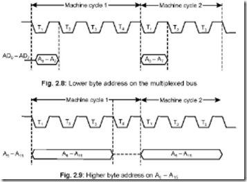
45. Draw the lower and higher order address bus during the machine cycles.

Ans. The lower byte of address (AD0 – AD7) is available on the multiplexed address/data bus during T1 state of each machine cycle, except during the bus idle machine cycle, shown in Fig. 2.8.

The higher byte of address (A8 – A15) is available during T1 to T3 states of each machine cycle, except during the bus idle machine cycle, shown in Fig. 2.9.
 

10-21-2014 8-25-14 PM


46. Draw the appearance of data in the read and write machine cycles.

Ans. Data transfer from memory or I/O device to microprocessor or the reverse takes place during T2 and T3 states of the machine cycles.

In the read machine cycle, data appears at the beginning of T3 state, whereas in the write machine cycle, it appears at the beginning of T2, shown in Fig. 2.10.


10-21-2014 8-25-50 PM

Fig. 2.10: Data bus

47. Draw the status signals during opcode fetch and memory read machine cycles.

clip_image026Ans. The status signals are IO/ M , S0 and S1. Their conditions indicate the type of machine cycle that the system is currently passing through. These three status signals remain active right from the beginning till the end of each machine cycle, shown in Fig. 2.11.


10-21-2014 8-26-11 PM

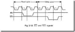
48. Show the RD and WR signals during the Read cycle and Write cycle.

Ans. When RD is active, microprocessor reads data from either memory or I/O device while

when WR is active, it writes data into either memory or I/O device.
10-21-2014 8-26-33 PM

Data transfer (reading/writing) takes place during T2 and T3 states of read cycle or write cycle and is shown in Fig. 2.12.

49. Indicate the different machine cycles of 8085.

Ans. 8085 has seven different machine cycles. These are:

(1) Opcode Fetch (2) Memory Read (3) Memory Write (4) I/O Read (5) I/O Write

(6) Interrupt Acknowledge (7) Bus Idle.

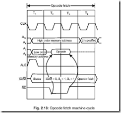
50. Draw the Opcode Fetch machine cycle of 8085 and discuss.

Ans. The first machine cycle of every instruction is the Opcode Fetch. This indicates the kind of instruction to be executed by the system. The length of this machine cycle varies between 4T to 6T states—it depends on the type of instruction. In this, the processor places the contents of the PC on the address lines, identifies the nature of machine cycle

(by IO/M , S0, S1) and activates the ALE signal. All these occur in T1 state.’’
 

10-21-2014 8-26-51 PM

In T2 state, RD signal is activated so that the identified memory location is read from

and places the content on the data bus (D0 – D7).

In T3, data on the data bus is put into the instruction register (IR) and also raises


the RD signal thereby disabling the memory.

In T4, the processor takes the decision, on the basis of decoding the IR, whether to enter into T5 and T6 or to enter T1 of the next machine cycle.

One byte instructions that operate on eight bit data are executed in T4. Examples are ADD B, MOV C, B, RRC, DCR C, etc.

51. Briefly describe Memory Read and Write machine cycles and show the wave- forms.
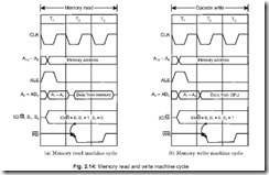
 

10-21-2014 8-27-10 PM


Fig. 2.14: Memory read and write machine cycle

Ans. Both the Memory Read and Memory Write machine cycles are 3T states in length. In Memory Read the contents of R/W memory (including stack also) or ROM are read while in Memory Write, it stores data into data memory (including stack memory).

As is evident from Fig. 2.14 during T2 and T3 states data from either memory or CPU are made available in Memory Read or Memory Write machine cycles respectively. The

clip_image021[1]status signal (IO/ M , S0, S1) states are complementary in nature in Memory Read and Memory Write cycles. Reading or writing operations are performed in T2.

In T3 of Memory Read, data from data bus are placed into the specified register (A,

B, C, etc.) and raises RD so that memory is disabled while in T3 of Memory Write

WR signal is raised which disables the memory.

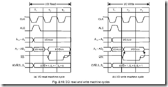
52. Draw the I/O Read and I/O Write machine cycles and discuss.

clip_image021[2]Ans. I/O Read and Write machine cycles are almost similar to Memory Read and Write machine cycles respectively. The difference here is in the IO/ M signal status which remains 1 indicating that these machine cycles are related to I/O operations. These machine cycles take 3T states.

In I/O read, data are available in T2 and T3 states, while during the same time (T2 and T3) data from CPU are made available in I/O write.

The I/O read and write machine cycles are shown in Fig. 2.15.
 

10-21-2014 8-27-28 PM

Fig. 2.15: I/O read and write machine cycles

53. Draw the Interrupt Acknowledge cycles for (a) RST instruction (b) CALL instruction.
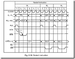
 

10-21-2014 8-27-43 PM


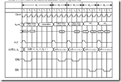
In M1, RST is decoded. This initiates a CALL to the specific vector location. Contents of the PC are stored in stack in machine cycles M2 and M3.
10-21-2014 8-27-57 PM

Fig. 2.17: Timing diagram of INTA machine cycle and execution of call instruction

The above figure shows an Interrupt Acknowledge cycle for CALL instruction. M2 and M3 machine cycles are required to call the 2 bytes of the address following the CALL. Memory write are done in machine cycles M4 and M5 in which contents of PC are stored in stack and then a new instruction cycle begins.

54. What is meant by Bus Idle Machine cycle?

Ans. There are a few situations in which machine cycles are neither Read or Written into.

These are called Bus Idle Machine cycle.

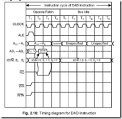
Such situations arise when the system executes a DAD or during the internal opcode generation for the RST or TRAP interrupts.

The ALE signal changes state during T1 of each machine cycle, but in Bus Idle Machine cycles, ALE does not change state.

55. Explain the DAD instruction and draw its timing diagram.

Ans. DAD instruction adds the contents of a specified register pair to the contents of H and L. For execution of DAD, 10 T-states are needed. Instead of having a single machine cycle having 10 T-states, it consists of the Opcode Fetch machine cycle (4T states) and 6

extra T-states divided into two machine cycles. These two extra machine cycles are Bus

Idle Machine cycles which do not involve either memory or I/O.
10-21-2014 8-28-19 PM

56. Discuss the concept of WAIT states in microprocessors.

Ans. So many times it may happen that there is speed incompatibility between microprocessor and its memory and I/O systems. Mostly the microprocessor is having higher speed.

So in a given situation, if the microprocessor is ready to accept data from a peripheral device while there is no valid data in the device (e.g. an ADC), then the system enters into WAIT states and the READY pin (an input pin to the microprocessor, pin no. 35 for 8085) is put to a low state by the device.

Once the device becomes ready with some valid data, it withdraws the low state on the READY pin of 8085. Then 8085 accepts the data from the peripheral by software instructions.

57. Does 8085 have multiplication and division instructions?

Ans. No, 8085 does not have the above two instructions. It can neither multiply nor divide two 8-bit numbers. The same are executed by the processor following the process of repetitive addition or subtraction respectively.

58. Indicate the bus drive capability of 8085.

Ans. 8085 buses can source up to 400 mA and sink 2 mA of current. Hence 8085 buses can drive a maximum of one TTL load.

Thus the buses need bus drivers/buffers to enhance the driving capability of the buses to ensure that the voltage levels are maintained at appropriate levels and malfunctioning is avoided.

59. What are the buffers needed with the buses of 8085?

Ans. An 8-bit unidirectional buffer 74LS244 is used to buffer the higher order address bus (A8 – A15). It consists of eight non-inverting buffers with tri-state outputs. Each pin can sink 24 mA and source 15 mA of current.

A bidirectional buffer 74LS245 (also called octal bus transreceivers) can be used to drive the bidirectional data bus (D0 – D7) after its demultiplexing. The DIR pin of the IC controls the direction of flow of data through it.

60. Explain the instruction cycle of a microprocessor.

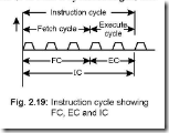
Ans. When a processor executes a program, the instructions (1 or 2 or 3 bytes in length) are executed sequentially by the system. The time taken by the processor to complete one instruction is called the Instruction Cycle (IC).

An IC consists of Fetch Cycle (FC) and an Execute Cycle (EC). Thus IC = FC + EC. It is shown in Fig. 2.19. Depending on the type of instruction, IC time varies.
10-21-2014 8-28-42 PM


61. Explain a typical fetch cycle (FC).

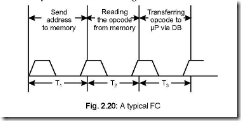
Ans. The time required to fetch an opcode from a memory location is called Fetch Cycle.

A typical FC may consist of 3T states. In the first T-state, the memory address, residing in the PC, is sent to the memory. The content of the addressed memory (i.e., the opcode residing in that memory location) is read in the second T-state, while in the third T-state this opcode is sent via the data bus to the instruction register (IR). For slow memories, it may take more time in which case the processor goes into ‘wait cycles’. Most microprocessors have provision of wait cycles to cope with slow memories.

A typical FC may look like the following:
10-21-2014 8-28-59 PM

62. Draw the block schematic of a typical Instruction Word flow diagram and explain the same.

Ans. There are two kinds of words—instruction word and data word. The 2 byte content of the PC is transferred to a special register–called memory address register (MAR) or simply address register (AR) at the beginning of the fetch cycle. Since the content of MAR is an address, it is thus sent to memory via the address bus. The content of the addressed memory is then read under ‘Read control’ generated by T&C section of the microprocessor. This is then sent via the data bus to the memory data register (MDR) or simply data register (DR) existing in CPU. This is placed in the instruction register (IR) and is decoded by the instruction decoder and subsequently executed. The PC is then incremented if the subsequent memory location is to be accessed.

10-21-2014 8-29-14 PM

63. Draw the block schematic of a typical data word flow diagram and explain the same.

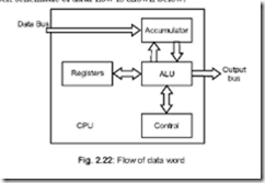
Ans. The data word flows via the data bus into the accumulator. The data source can be a memory device or an input device. Data from the accumulator is then manipulated in ALU under control of T & C unit. The manipulated data is then put back in the accumulator and can be sent to memory or output devices.

The block schematic of data flow is shown below.
10-21-2014 8-29-27 PM

64. Why a microprocessor based system is called a sequential machine?

Ans. It can perform the jobs in a sequential manner, one after the other. That is why it is called a sequential machine.

65. Why a microprocessor based system is called a synchronous one?

Ans. All activities pertaining to the µP takes place in synchronism with the clock. Hence it is called a synchronous device.

66. Draw the diagram which will show the three buses separately, with the help of peripheral ICs.

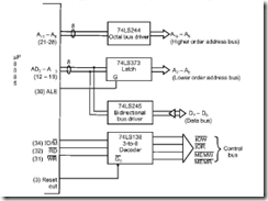
Ans. The scheme of connections is shown below. The octal bus driver 74LS244 drives the higher order address bus A15 – A8 while 74LS373 Latch drives the lower order address bus A7 – A0 (with the help of ALE signal). The bidirectional bus driver 74LS245 drives the

data bus D7 – D0 while the 74LS138 (a 3 to 8 decoder chip) outputs at its output pins IOW, IOR, MEMW, MEMR, signals from the IO/ M , RD and WR signals of 8085.
10-21-2014 8-29-49 PM

Fig. 2.23: Demultiplexing of address/data bus and separation of control signals

67. Discuss the status of WR and RD signals of 8085 at any given instant of time.

Ans. At any given instant, the status of the two signals WR and RD will be complementary

to each other.

It is known that microprocessor based system is a sequential device, so that at any given point of time, it does the job of reading or writing—and definitely not the two jobs

at the same time. Hence if WR signal is low, then RD signal must be high or vice versa.

68. Which registers of 8085 are programmable?

Ans. The registers B, C, D, E, H and L are programmable registers in that their contents can be changed by programming.

69. Suggest the type of operations possible on data from a look of the architecture of 8085.

Ans. The architecture of 8085 suggests that the following operations are possible.

z Can store 8-bits of data.

z Uses the temporary registers during arithmetic operations.

z Checks for the condition of resultant data (like carry, etc.) from the flag register.

70. What are the externally initiated operations supported by 8085?

Ans. 8085 supports several externally initiated operations at some of its pins. The operations possible are:

z Resetting (via Reset pin)

z Interruptions (via Trap, RST 7.5, RST 6.5, RST 5.5 and Interrupt pin)

z Ready (via Ready pin)

z Hold (via Hold pin)

71. Name the registers not accessible to the programmer. Ans. The following registers cannot be accessed by the programmer:

z Instruction register (IR)

z Memory address register (MAR) or supply address register (AR)

z Temporary registers.

72. Name the special purpose registers of 8085.

Ans. The special purpose registers used in 8085 microprocessor are:

z Accumulator register (A)

z Program counter register (PC)

z Status (or Flag) register

z Stack pointer register (SP)

73. What should be the size of the Instruction Register if an arbitrary microprocessor has only 25 instructions?

Ans. The length of the Instruction Register would be 5-bits, since 25 = 32, since a 5-bit Instruction Register can decode a maximum of 32 instructions.

74. Explain the difference between HLT and HOLD states.

Ans. HLT is a software instruction. Its execution stops the processor which enters into a HALT state and the buses of the processor are driven into tri-state.

HOLD is an hardware input to the processor. When HOLD input = 1, the processor goes into the HOLD state, but the buses don’t go into tri-state. The processor gives out a high HLDA (hold acknowledge) signal which can be utilised by an external device (like a DMA controller) to take control of the processor buses. HOLD is acknowledged by the processor at the end of the current instruction execution.

75. Indicate the length of the Program Counter (PC) to access 1 KB and 1 MB memory.

Ans. 1 KB = 1024 bytes

and 1 MB = 1024 K bytes

Thus the required number of bits in PC to access 1 KB are 10 (210 = 1024) and 20 (220 = 1024 K) respectively.

76. What determines the number of bytes to be fetched from memory to execute an instruction?

Ans. An instruction normally consists of two fields. These are:

10-21-2014 8-30-06 PM


Thus, while the system starts executing an instruction, it first decodes the opcode which then decides how many more bytes are to be brought from the memory—its minimum value is zero (like RAR) while the maximum value is two (like STA 4059 H).

77. A Microprocessor’s control logic is ‘microprogrammed’. Explain.

Ans. It implies that the architecture of the control logic is much alike the architecture of a

very special purpose microprocessor.

78. Does the ALU have any storage facility?

Ans. No, it does not have any storage facility. For this reason, the need for temporary data

registers arise in ALU–it has two inputs: one provided by the accumulator and the other

from the temporary data register. The result of summation is stored in the accumulator.
 

Microprocessor, Microcomputer and Associated Languages

Microprocessor, Microcomputer and Associated Languages

1. On which model is based the basic architecture of a digital computer? Ans. The basic architecture of a digital computer is based on Von Neumann model.

2. What is meant by distributed processing?

Ans. Distributed processing involves the use of several microprocessors in a single computer system. For example, for such a system, the first microprocessor may control keyboard activities, the second controls storage devices like disk drives, the third controls input/ output operations, while the fourth may act as the main system processor.

3. When was the first microprocessor developed?

Ans. The first microprocessor was developed by BUSICOM of Japan and INTEL of USA in the year 1971.

4. What is a microprocessor?

Ans. A microprocessor may be thought of as a silicon chip around which a microcomputer is built.

5. What is the technology used in microprocessors? Ans. NMOS technology is used in microprocessors.

6. What are the three main units of a digital computer?

Ans. The three main units of a digital computer are: the central processing unit (CPU), the memory unit and the input/output devices.

7. How does the microprocessor communicate with the memory and input/output devices?

Ans. The microprocessor communicates with the memory and the Input/Output devices via the three buses, viz., data bus, address bus and control bus.

8. What are the different jobs that the CPU is expected to do at any given point of time?

Ans. The CPU may perform a memory read or write operation, an I/O read or write operation or an internal activity.

9. What is a mnemonic?

Ans. It is very difficult to understand a program if it is written in either binary or hex code.

Thus the manufacturers have devised a symbolic code for each instruction, called a

mnemonic.

Examples of mnemonics are: INR A, ADD M, etc.

10. What is machine language programming?

Ans. Programming a computer by utilising hex or binary code is known as machine language programming.

11. What is meant by assembly language programming?

Ans. Programming a microcomputer by writing mnemonics is known as assembly language programming.

12. What are meant by low level and high level languages?

Ans. Programming languages that are machine dependent are called low level languages. For example, assembly language is a low level language.

On the other hand, programming languages that are machine independent are called high level languages. Examples are BASIC, FORTRAN, C, ALGOL, COBOL, etc.

13. What is meant by ‘word length’ of a computer?

Ans. The number of bits that a computer recognises and can process at a time is known as its ‘word length’.

14. What is meant by instruction?

Ans. An instruction is a command which asks the microprocessor to perform a specific task or job.

15. How many different instructions mP 8085 has? What is an instruction set?

Ans. 8085 microprocessor has a total of 74 different instructions for performing different operations or tasks.

The entire different instructions that a particular microprocessor can handle is called its instruction set.

16. What an instruction consists of?

Ans. An instruction consists of an operation code (called ‘opcode’) and the address of the data (called ‘operand’), on which the opcode operates.

10-21-2014 8-00-21 PM


17. Give one example each of the different types of instructions.

Ans. Instructions can be of (i) direct (ii) immediate (iii) implicit type. Examples of each type follows:

(i) direct type : LDA 4000

(ii) immediate type : MVIA, 1F

(iii) implicit type : ADD C

18. What language a microprocessor understands? Ans. Microprocessor understands only binary language.

19. How the mnemonics written in assembly language are translated into binary?

Ans. The translation from assembly language (i.e., mnemonics) into binary is done either manually (known as hand (or manual) assembly) or by a program called an assembler.

Thus an assembler can be thought of as a program which translates the mnemonics entered by an ASCII keyboard into its equivalent binary code, which is the only one understood by a microprocessor.

20. How an assembler translates programs written in mnemonic form to binary?

Ans. An assembler has a ‘translation dictionary’, which is stored in its memory. Mnemonics entered via keyboard is compared with this dictionary, which then retrieves its binary equivalent from the same place (dictionary).

21. What are the types of mnemonics possible?

Ans. Mnemonics can be of two types—alphabetical or alphanumerical.

Example of first type is ADD D whereas, MVI A, 0F is an example of the second category.

22. What are source codes and object codes?

Ans. High level languages (like, BASIC, COBOL, ALGOL, etc.) are called source codes, whereas binary language is called object code.

23. How are high level languages converted into binary?

Ans. The high level languages are converted into their corresponding binary by means of another program, called either a compiler or an interpreter.

Compilers are generally used for FORTAN, PASCAL, COBOL, etc. whereas

interpreters are generally used in BASIC. M-BASIC is a common example of an

interpreter for BASIC language.

24. What is a ‘statement’?

Ans. Instructions written in high level languages are known as statements.

25. Write down the difference between a compiler and an interpreter.

Ans. Difference between a compiler and an interpreter lies in the generation of the machine code or object code.

A compiler reads the entire program first and then generates the corresponding object code.

Whereas, an interpreter reads an instruction at a time, produces the corresponding object code and executes the same before it starts reading the next instruction. A program from a compiler runs some 5 to 25 times faster than a program from an interpreter.

26. Differentiate between a compiler/interpreter and an assembler. Ans.

S.No.

Compiler/Interpreter

Assembler

1.

Debugging easier

Debugging relatively tougher

2.

Less efficient

More efficient

3.

Requires large memory space

Requires less memory space

As an example, for gadget controls and traffic signals, assembly language programming is done because programs in such cases are compact and not lengthy. But for cases where large program lengths are a must, compilers/interpreters are used. For such a case, although a large memory space is required, the advantage lies in very quick debugging.

27. What are the names given to instructions written in high and low level languages?

Ans. The instructions written in high level languages are known as ‘statements’ whereas those written in low level languages are called ‘mnemonics’.

28. What is another name of a microprocessor?

Ans. A microprocessor is also called the CPU, the central processing unit.

29. What is a microcomputer?

Ans. A microcomputer is a system which is capable of processing a stream of input informations and will generate a stream of output informations taking the help of a program which is stored in the memory of the system.

30. What are the jobs that a microcomputer is capable of doing? How does it do the jobs?

Ans. A microcomputer is capable of doing the following jobs:

(a) receiving input (in the form of data or instruction).

(b) performing computations, both arithmetic and logical.

(c) storing data and instructions.

(d) displaying the results of any computations.

(e) controlling all the devices that perform the above mentioned four tasks, either

directly or indirectly.

The first task is done by an input device, whereas the second job is done by the arithmetic logic unit (ALU). The third task is done by the memory unit while an output device does the fourth job.

The fifth job is executed by the timing and control (T&C) unit.

31. What is a bus?

Ans. A bus is a bunch of wires through which data or address or control signals flow.

32. What are the different buses and what jobs they do in a microprocessor?

Ans. The different buses in a microprocessor are the data bus (DB), address bus (AB) and the control bus (CB). Data flow through the DB, while address comes out of the AB and CB controls the activities of the microcomputer system at any instant of time.

33. Why are the different buses buffered?

Ans. A buffer enhances the current or power driving capability of a pin of an IC.

34. In how many ways computers are divided?

Ans. Computers are divided into three categories as per the superiority and number of microprocessors used. These are:

z Micro computers

z Mini computers

z Mainframe computers

35. Distinguish between the three types of computers.

Ans. A microcomputer is a small computer containing only a single central processing unit (CPU). Their word length varies between 8 and 32 bits and used in small industrial and process control systems. The storage capacity and speed requirements of micro­ computers are moderate.

Mini computers are having more storage capacity and more speed than micro computers. Mini computers are used in research, data processing, scientific calculations etc.

Mainframe computers are designed to work at very high speed and they have very high storage capacity. Their word length is typically 64-bits. These are used for research, data processing, graphic applications, etc.

36. In how many ways computer softwares are categorised?

Ans. Computer softwares are divided into two broad categories—system software and user software.

37. Explain the two types of softwares.

Ans. System software is a collection of programs used for creation, preparation and execution of other programs. Editors, assemblers, loaders, linkers, compilers, interpreters, debuggers and OS (operating system) are included in system software.

User software are softwares developed by various users.

38.Draw the software hierarchy of a microcomputer system. Ans. The software hierarchy is shown below:

10-21-2014 7-59-56 PM

Fig. 1.1: Software hierarchy of a microcomputer system

39. What is an editor?

Ans. An editor is a program and is used for creation and modification of source programs or text. The editor program includes commands which can delete, insert or change lines/ characters.

An editor stores in ASCII form in successive RAM locations of the typed letters/ numbers. This then can be saved by the SAVE command on a floppy or hard disk. The editor can load the program on RAM later for corrections/alterations, if necessary.

40. What is an OS (operating system) and what are its functions?

Ans. An operating system provides an interface between the end user and the machine. It performs the function of resource management. By ‘resource’ is meant a microprocessor, memory or an I/O device.

An OS is a collection of a set of programs that manages machine functions under varied conditions.

The different functions performed by the OS include an efficient or effective way of sharing memory, I/Os and the CPU amongst different users. Today, operating systems are DOS, UNIX, WINDOWS, etc.

41. What are the different types of assemblers used?

Ans. The different assemblers used are: (a) Macro Assembler, (b) Cross Assembler, (c) Meta Assembler.

42. What is a linker?

Ans. A linker is a program that links several small object files to produce one large object file.

A large program is usually divided into several small programs. They are written separately, tested and debugged. The large program is then produced by linking these debugged programmes.

A linker has a link file and a link map. The former contains the binary codes of all the modules which have been combined while the link map stores in it the addresses of all the link files. A linker assigns relative addressing instead of absolute addressing which helps in putting a linker program anywhere in the memory.

43. What is a locator?

Ans. A locator is a program which is used to assign specific address when object code is to be loaded into the memory.

44. What are the different assembly languages used for 8085 microprocessor?

Ans. Two different assembly languages are used for 8085 microprocessor—one is used by the manufacturer INTEL and the other defined in IUL 77.

45. What is a coprocessor?

Ans. A coprocessor or an arithmetic coprocessor, as it is so called, performs operations like exponentiation, trigonometric functions, etc. To implement these functions in CPU hardware is a costly one and the software implementation of the above slows down the processor. A coprocessor overcomes these difficulties.

The coprocessor has its own instruction set. The CPU and the coprocessor execute their respective instructions from the same program.

The instructions belonging to the coprocessor are fetched and decoded by the CPU but executed by the coprocessor.

46. Draw a typical coprocessor configuration and discuss the same. Ans. A typical coprocessor configuration looks like as follows:

image

The CPU and the coprocessor share the same clock, bus control logic and also share the entire memory and the I/O subsystem. In normal configuration, CPU is the master and the coprocessor is the slave.

The CPU treats the coprocessor as an external memory in the sense that the CPU can read from/write into the coprocessor registers in a manner alike that of an external memory. The CPU and the coprocessor executes their instructions independent of each other. When the coprocessor executes instructions, it indicates the CPU about its

executions via the ‘BUSY’ signal.

47. What is a coprocessor trap?

Ans. When a coprocessor is not connected in the system and the functions of the coprocessor is done by the CPU by writing coprocessor instructions from a predetermined location in the form of a software routine and invoked by interrupt, it is known as ‘coprocessor trap’.

48. Explain the three fields contained in a coprocessor instruction.

Ans. There are three fields in a coprocessor instruction—these are code, address and opcode.

The code field distinguishes between the coprocessor and CPU instructions. The address field indicates the address of a particular coprocessor. This is required when several coprocessors are used in the system. The opcode field indicates the type of operation to be executed by the processor.

49. What is a debugger?

Ans. A debugger is a program that debugs an object code program by placing it into the system memory and subsequently executing the same.

50. How does a debugger help in debugging a program?

Ans. A debugger is a software tool which isolates the problems/drawbacks in a programmer’s program.

A debugger helps in debugging a program in the following ways:

(a) A debugger helps in checking the contents of memory locations and various registers and

also alter the same if required and rerun the program to check the correctness of the

modified program.

(b) Program execution can be stopped after each instruction–hence step by step checking is

possible with a debugger.

(c) A debugger can set a breakpoint at any place in a program.

A program then can run up to the breakpoint address and not beyond. Thus any fault

in the program up to the breakpoint address can be checked by having a look at the

various registers and memory contents. If no fault occurs the breakpoint is set at a latter

address in the program and the debugger can again be rerun to check for the correctness

of the program. This way the whole program can be corrected by judiciously inserting

breakpoints in a program.

51. What is meant by the term ‘word’?

Ans. A collection of bits is called a word. A word does not have a fixed number of bits—unlike

the case of byte (= 8 byte) or a nibble (= 4 bytes).

For different microprocessors, the word length varies. For example, for 8-bit

microprocessors, the word length is 8-bits while that for 32-bit microprocessors, the word

length is 32-bits.

A word is expressed usually in multiples of 2, but no value is excluded. That is, we

can have a 19-bit word or 37-bit word, etc.

52. What is meant by the term ‘long word’?

Ans. The term ‘long word’ means a group of bits twice the normal length of the

microprocessor. Hence, for a 16-bits microprocessor like 8086, a long word means

a group consisting of 32-bits.

53. Distinguish between KB, MB, GB, TB and PB.

Ans. These stand for Kilobyte, Megabyte, Gigabyte, Terabyte and Petabyte respectively.

1 KB

=

1024 bytes

=

210 bytes

1 MB

=

1 Kilo KB

=

220 bytes

1 GB

=

1 Kilo MB

=

230 bytes

1 TB

=

1 Kilo GB

=

240 bytes

1 PB

=

1 Kilo TB

=

250 bytes

54. Compare signed magnitude number and complementary numbers. Ans. The comparison is made on the basis of an 8-bit word.

In signed magnitude number system, MSB represents the sign of the number with 1 and 0 representing minus and plus, respectively. This number system has the following drawbacks:

Using the MSB for sign bit leaves 7-bits for data which can range from 0 to 12710 ( = 11111112) while 8-bits can manage numbers from 0 to 25510 (=1111 11112).

Addition of two signed numbers does not give the correct result always. An example follows:


10-21-2014 8-03-09 PM


Thus the result of addition of the two numbers is –0710, but it should have been

+13510.

Use of complementary numbers (usually 2’s complement of a binary number is used)

gives rise to the following advantages:

z For an 8-bit data, the data values can vary from 0 to 25510 (= 1111 11112)

z Addition and subtraction can be implemented with almost same circuitry.

55. What is meant by normalising a number?

Ans. When a number 4751 is converted to 4.751×10³, the latter is called the normalised version

of the former.

Likewise, in binary, a number 1011 1101 can be normalised to 1.0111101 × 28.

Another binary number 0.0001101 is normalised to 1.101 × 2–4.

If a given binary number is in a form 1.0101101, then it is already in the normalised

form.

56. Name the different parts of a normalised number. Ans. Let a binary number is 1.01101 × 10¹¹. Then


10-21-2014 8-03-35 PM


Hence, a normalised binary number consists of mantissa, radix and exponent.

57. Discuss the utility of floating point numbers.

Ans. Floating point numbers are useful when the system has either to handle extremely large

numbers (as in Astronomy) or very small ones (as in Nuclear Physics). For floating point

numbers, the binary number starts with a 1, followed by the binary point. An 8-bit binary

mantissa can assume extreme values as 1.0000000 to 1.1111111.

While storing such floating point numbers, the mandatory 1 followed by the binary

point can safely be ignored—thereby saving previous storage space. It is assumed that

the 1 and the binary point are just present. Thus the above can now be stored as 0000000

to 1111111.

For floating point numbers, a 32-bit storage area is used. Many variants are there

to fill in these 32-bits, but the following figure is the one that is most sought after.


10-21-2014 8-03-51 PM


Fig. 1.3: Floating point numbers—32-bit storage area

Bit 0 is the sign bit for the mantissa. Bits 1 to 23 hold the mantissa while bits 24 to 31 hold the exponent of the number. The eight bits (bits 24 to 31) are used to hold the numbers from –127 to +128 in 2’s complement form or Excess –127 form. In Excess –127 notation, 127 is added to the original exponent value (in decimal)—this is done to get rid of the negative exponent values. Thus this modified exponent value (positive) is stored in bits 24 to 31 after it is converted into binary.

58. Discuss speed, size and accuracy while handling floating point numbers.

Ans. Floating point operations that can be carried out per second is a measure of the speed—

abbreviated as FLOPS.

Accuracy is dependent on the number of mantissa bits. More number of mantissa

bits result in more accuracy. Bits 1 to 23, meant for mantissa, can have a maximum

binary value of 1.1111 1111 1111 1111 1111 111. The 1’s, starting from the binary point

on the right, have their decimal values +0.5, +0.25, +0.125, +0.0625, etc. Thus, when

the 24-bits are converted into decimal, it will approach a value of 2 — but will never

equal it. If more number of bits are accommodated in mantissa (i.e., mantissa will now

have more than the normal 24-bits), then the converted decimal equivalent will be

having a value which will be even more closer to 2. Thus increasing number of mantissa

bits result in more accuracy.

Size is dependent on the number of exponent bits. More number of exponent bits

results in greater size of the number that can be handled. Bits 24 to 31, meant for

exponent, has eight bits ranging from –127 to +128. Thus the maximum number that can be handled is 1 × 2128 = 3.4 × 1038 roughly. This value would have been more if in case more number of bits are accommodated into exponent bits. Thus increasing number of exponent bits results in greater size of the number that can be handled. In conclusion, when more accuracy is demanded, number of mantissa bits are to be increased (instead of the normal 24-bits) and in cases of higher size of data handling, number of exponent bits are to be increased (instead of the normal 8-bits) within the 32-bit storage space.

59. Explain single and double precision.

Ans. Single and double precision mean 32-bits and 64-bits storage areas respectively. The

extra storage space made available from single to double precision—utilised for

accommodating more number of mantissa bits—would result in much more accuracy from the system.

60. List the different generation languages.

Ans. These are first, second, third and fourth generation languages. Machine code belongs to

first generation, while Assembly Language belongs to second generation language. First

and second generation languages are known as low level languages. Third generation languages include FORTRAN, BASIC, COBOL, PASCAL, C, C++, JAVA while fourth generation languages are LISP, APL, PROLOG, etc.


10-21-2014 8-04-14 PM


Fig. 1.4: The different languages


AC motor What It Does,How It Works,Variants,Values,How to Use it and What Can Go Wrong

The distinction between AC and DC motors has become blurred as controllers for DC motors make increasing use of pulse-width modulation, which can be viewed as a form of alternating current. All motors that consume DC power are referenced in the DC mo­tor section of this encyclopedia, regardless of whether they modulate the power inter­nally. Stepper motors and servo motors are considered as special cases, each with its own entry. AC motors, described here, are those that consume alternating current, usu­ ally in the form of a sine wave with a fixed frequency.

What It Does

An AC motor uses a power supply of alternating current to generate a fluctuating magnetic field that turns a shaft.

How It Works

The motor consists primarily of two parts: the stator, which remains stationary, and the rotor, which rotates inside the stator. Alternating cur­ rent energizes one or more coils in the stator, creating fluctuating magnetic fields that interact with the rotor. A simplified representation is shown in Figure 23-1, where the coils create mag­ netic forces indicated by the green arrows, N rep­ resenting North and S representing South.

Stator Design

Plug-in electric fans typically use AC motors. The stator from a large electric fan is shown in Figure 23-2, where the large diameter of each coil

clip_image004

Figure 23-1. A simplified representation of a basic AC motor. The green arrows indicate magnetic force.

maximizes its magnetic effect. The stator from a smaller electric fan is shown in Figure 23-3, in which only one coil is used. (The coil is wrapped in black electrical tape.)

clip_image007

Figure 23-2. The stator from a large electric fan. Each coil of copper wire is centered on a lug pointing inward to the hole at the center, where the rotor would normally be mounted. The coils overlap because their diameter is maximized to increase their magnetic effect. Each coil is tapped to allow speed selection in steps via an external rotary switch.

The core of a stator resembles the core of a transformer in that it usually consists of a stack of wafers of high-silicon steel (or sometimes alu­minum or cast iron). The layers are insulated from one another by thin layers of shellac (or a similar compound) to prevent eddy currents that would otherwise circulate through the entire thickness of the stator, reducing its efficiency.

The coil(s) wound around the stator are often re­ ferred to as field windings, as they create the magnetic field that runs the motor.

Rotor Design

In most AC motors, the rotor does not contain any coils and does not make any electrical con­

clip_image009

Figure 23-3. This stator from a smaller electric fan uses only a single coil, wrapped in black tape. It is sufficient to induce a magnetic field but is generally less efficient than a motor using multiple coils.

nection with the rest of the motor. It is powered entirely by induced magnetic effects, causing this type of motor to be known generally as an induction motor.

As the AC voltage changes from positive to neg­ative, the magnetic force induced in the stator collapses and a new field of opposite polarity is created. Because the stator is designed to create an asymmetrical field, it induces a rotating mag­netic field in the rotor. The concept of a rotating magnetic field is fundamental in AC motors.

Like the stator, the rotor is fabricated from wafers of high silicon steel; embedded in the wafers are nonmagnetic rods, usually fabricated from alu­minum but sometimes from copper, oriented approximately parallel to the axis of rotation. The rods are shorted together by a ring at each end of the rotor, forming a conductive “cage,” which explains why this device is often referred to col­loquially as a squirrel cage motor.

Figure 23-4 shows the configuration of a rotor cage with the surrounding steel wafers removed for clarity. In reality, the rods in the cage are al­ most always angled slightly, as shown in Figure 23-5, to promote smooth running and re­ duce cogging, or fluctuations in torque, which would otherwise occur.

clip_image012

Figure 23-4. The rotor of a typical AC motor contains a cage of aluminum (or sometimes copper) in which eddy currents occur, as a result of the rotating magnetic field inside the steel body of the rotor (which is omitted here for clarity). These currents cause their own magnetic fields, which interact with the fields generated by coils in the stator.

In Figure 23-6, the steel wafers of a rotor are shown, with channels to accommodate an an­gled aluminum cage. Figure 23-7 shows a cross- section of a rotor with the cage elements in pale red and the steel wafer in gray.

clip_image014

Figure 23-5. To promote smooth running of the motor, the longitudinal elements of the cage are typically angled, as suggested in this rendering.

clip_image016

Figure 23-6. The steel wafers in the rotor of an AC motor are typically offset as shown here. The channels are to ac- commodate a cage of aluminum or copper conductors.

clip_image019

Figure 23-7. Cross-section of a rotor with steel shown in gray and embedded elements of an aluminum cage shown in pale red.

The actual rotor from an induction motor is shown in Figure 23-8. This rotor was removed from the stator shown in Figure 23-3. The bear­ ings at either end of the rotor were bolted to the stator until disassembly.

Although the cage is nonmagnetic, it is electri­cally conductive. Therefore the rotating magnet­ic field that is induced in the steel part of the rotor generates substantial secondary electric current in the cage, so long as the magnetic field inside the rotor is turning faster than the rotor itself. The current in the longitudinal elements of the cage creates its own magnetic field, which interacts with the fields created by coils in the stator. At­ traction and repulsion between these fields causes the rotor to turn.

Note that if the turning speed of the rotor rises to match the frequency of the alternating current powering the coils in the stator, the cage in the rotor is no longer turning through magnetic lines of force, and ceases to derive any power from

clip_image021Figure 23-8. The rotor from a small fan motor. The aluminum cage and its end pieces are the pale gray sections, steel plates are the darker sections.

them. In an ideal, frictionless motor, its unloaded operating speed would be in equilibrium with the AC frequency. In reality, an induction motor never quite attains that speed.

When power is applied while the rotor is at rest, the induction motor draws a heavy surge of cur­ rent, much like a short-circuited transformer. Electrically, the coils in the stator are comparable to the primary winding of a transformer, while the cage in the rotor resembles the secondary winding. The turning force induced in the sta­tionary rotor is known as locked-rotor torque. As the motor picks up speed, its power consump­tion diminishes. See Figure 23-9.

When the motor is running and a mechanical load is applied to it, the motor speed will drop. As the speed diminishes, the cage of conductors embedded in the rotor will derive more power, as they are turning more slowly than the rotating magnetic field. The speed of rotation of the field is determined by the frequency of the AC power, and is therefore constant. The difference in rota­

clip_image023

Figure 23-9. An approximated graph showing the typical current consumption of an AC induction motor as it starts from rest and gains speed over a period of time.

tional speed between the magnetic field and the rotor is known as slip. Higher levels of slip induce greater power, and therefore the induction mo­tor will automatically find an equilibrium for any load within its designed range.

When running under full load, a small induction motor may have a slip value from 4 to 6 percent. In larger motors, this value will be lower.

Variants

Variants of the generic induction motor de­ scribed above are generally designed to take ad­ vantage of either single-phase or three-phase al­ ternating current.

A synchronous motor is a variant in which the ro­ tor maintains a constant speed of rotation re­gardless of small fluctuations in load.

Some AC motors incorporate a commutator, which allows an external connection to coils mounted on the rotor, and can enable variable speed control.

A linear motor may consist of two rows of coils, energized by a sequence of pulses that can move a permanent magnet or electromagnet between the coils. Alternatively, the linear motor’s coils may move as a result of magnetic interaction with a segmented fixed rail. Detailed description of linear motors is outside the scope of this en­ cyclopedia.

Single-Phase Induction Motor

The majority of induction motors run on single- phase alternating current (typically, from domes­ tic wall outlets). This type of motor is not innately self-starting because the stator coils and rotor are symmetrical. This tends to result in vibration rather than rotation.

To initiate rotation, the stator design is modified so that it induces an asymmetrical magnetic field, which is more powerful in one direction than the other. The simplest way to achieve this is by adding one or more shorting coils to the stator. Each shorting coil is often just a circle of heavy- gauge copper wire. This ploy reduces the effi­ciency of the motor and impairs its starting tor­ que, and is generally used in small devices such as electric fans, where low-end torque is unim­portant. Because the shorting coil obstructs some of the magnetic field, this configuration is often known as a shaded pole motor.

Copper shorting coils are visible in the fan motor shown in Figure 23-3.

A capacitor is a higher-cost but more efficient alternative to a shorting coil. If power is supplied to one or more of the stator coils through a ca­pacitor, it will create a phase difference between these coils and the others in the motor, inducing an asymmetrical magnetic field. When the motor reaches approximately 80% of its designed run­ning speed, a centrifugal switch may be included to take the capacitor out of the circuit, since it is no longer necessary. Switching out the capacitor and substituting a direct connection to the stator coils will improve the efficiency of the motor.

A third option to initiate rotation is to add a sec­ond winding in the stator, using fewer turns of smaller-gauge wire, which have a higher resist­ ance than the main winding. Consequently the magnetic field will be angled to encourage the motor to start turning. This configuration is known as a split-phase induction motor, in which the starter winding is often referred to as the auxilliary winding and consists of about 30% of the total stator windings in the motor. Here again, a centrifugal switch can be incorporated, to eliminate the secondary winding from the cir­cuit when the motor has reached 75 to 80 per­ cent of its designed running speed.

The relationship between motor speed and tor­que of the three types of motors described above is shown in Figure 23-10. These curves are sim­plified and do not show the effect that would be produced by introducing a centrifugal switch.

clip_image025

Figure 23-10. Approximate curves showing the relation- ship between speed and torque for three types of single- phase induction motor. (Graph derived from AC Induction Motor Fundamentals published by Microchip Technology Inc.)

Three-Phase Induction Motor

Larger induction motors are often three-phase

devices. Three-phase AC (which is by far the most

common form of polyphase AC) is delivered by a power utility company or generator via three wires, each of which carries alternating current with a phase difference of 120 degrees relative to the other two, usually for industrial applica­ tions. A common configuration of stator coils for a three-phase motor is shown in Figure 23-11. Since the three wires take it in turns to deliver their peak voltage, they are ideally suited to turn the stator of a motor via induction, and no shorting coil or capacitor is needed for startup. Heavy- duty 3-phase induction motors are extremely re­ liable, being brushless and generally maintenance-free.

Synchronous Motor

A synchronous motor is a form of induction mo­ tor that is designed to reach and maintain equi­librium when the rotor is turning in perfect syn­ chronization with the AC power supply. The speed of the motor will depend on the number of poles (magnetic coils) in the stator, and the number of phases in the power supply. If R is the RPM of a synchronous motor, f is the frequency of the AC current in Hz, and p is the number of poles per phase:

R = (120 * f) / p

This formula assumes 60Hz AC current. In nations where 50Hz AC is used, the number 120 should be replaced with the number 100.

Two basic types of synchronous motors exist: di­ rect current excited, which require external power to start turning, and non-excited, which are self- starting. Since non-excited synchronous motors are more common in electronic applications, this encyclopedia will not deal with direct current ex­ cited variants.

A hysteresis motor is a synchronous motor con­ taining a solid rotor cast from cobalt steel, which has high coercivity, meaning that once it is mag­ netized, a substantial field is required to reverse the magnetic polarity. Consequently the polarity of the rotor lags behind the constantly changing

clip_image027

Figure 23-11. The graph shows voltage delivered via three wires constituting a three-phase power supply. (The curve colors are arbitrary.) A three-phase motor contains a multiple of three coils—often six, as shown here diagrammatically. The three wires of the power supply are connected directly to the coils, which induce a rotating magnetic field.

polarity of the stator, creating an attracting force that turns the rotor. Because the lag angle is in­ dependent of motor speed, this motor delivers constant torque from startup.

Reluctance Motor

Reluctance is the magnetic equivalent to electri­cal resistance. If a piece of iron is free to move in a magnetic field, it will tend to align itself with the field to reduce the reluctance of the magnetic

circuit. This principle was used in very early reluctance motors designed to work from AC and has been revived as electronics to control vari­able frequency drives have become cheaper.

The simplest reluctance motor consists of a soft iron rotor with projecting lugs, rotating within a stator that is magnetically energized with its own set of inwardly projecting poles. The rotor tends to turn until its lugs are aligned with the poles of the stator, thus minimizing the reluctance.

A basic reluctance motor design is shown in Figure 25-2. It is located in the stepper motor section of this encyclopedia, as stepper motors are a primary application of the reluctance prin­ciple.

Although a reluctance motor can be used with polyphase fixed-frequency AC power, a variable frequency drive greatly enhances its usefulness. The timing of the frequency is adjusted by the speed of the motor, which is detected by a sensor. Thus the energizing pulses can remain “one step ahead” of the rotor. Since the rotor is not a mag­ net, it generates no back-EMF, allowing it to reach very high speeds.

The simplicity of the motor itself is a compensat­ing factor for the cost of the electronics, as it re­ quires no commutator, brushes, permanent magnets, or rotor windings. Characteristics of re­ luctance motors include:

• Cheap parts, easily manufactured, and high reliability.

• Compact size and low weight.

• Efficiencies greater than 90% possible.

• Capable of high start-up torque and high speed operation.

Disadvantages include noise, cogging, and tight manufacturing tolerances, as the air gap be­ tween the rotor and stator must be minimized.

A reluctance motor can function synchronously, if it is designed for that purpose.

Variable Frequency Drive

A basic induction motor suffers from significant problems. The surge of power that it draws when starting from rest can pull down the supply volt­ age enough to affect other devices that share the AC power supply. (Hence, the brief dimming of lights that may occur when the compressor in an air conditioner or refrigerator starts running.) While the motor is turning, it can introduce elec­trical noise, which feeds back into the power supply, once again causing potential problems for other devices. In addition, the narrow range of speed of an AC induction motor is a great dis­ advantage.

The advent of cheap solid-state technology en­couraged the development of variable-frequency power supplies for induction motors. Because the impedance of the motor will diminish as the fre­quency diminishes, the current drawn by the motor will tend to increase. To prevent this, a variable frequency supply also varies the voltage that it delivers.

Wound-Rotor AC Induction Motor

The stator of this variant is basically the same as that of a single-phase induction motor, but the rotor contains its own set of coils. These are elec­trically accessible via a commutator and brushes,

as in a DC motor. Because the maximum torque

(also known as pull-out torque) will be prop or ­tional to the electrical resistance of the coils in the rotor, the characteristics of the motor can be adjusted by adding or removing resistance ex­ternally, via the commutator. A higher resistance will enable greater torque at low speed when the slip between the rotor speed and rotation of the magnetic field induced by the stator is greatest. This is especially useful in corded power tools such as electric drills, where high torque at low speed is desirable, yet the motor can accelerate to full speed quickly when the external resistance is reduced. Typically, the resistance is adjusted via the trigger of the drill.

Figure 23-12 shows a wound-rotor AC induction motor. The disadvantage of this configuration is

the brushes that supply power to the rotor will eventually require maintenance. Much larger wound-rotor motors are also used in industrial applications such as printing presses and eleva­ tors, where the need for variable speed makes a simple three-phase motor unsuitable.

clip_image029

Figure 23-12. A motor in a corded electric drill uses coils in a brushed rotor to enable variable speed output. In most AC motors, the speed is not adjustable and the rotor does not make any electrical connection with the rest of the motor.

Universal Motor

A wound-rotor motor may also be described as a universal motor if its rotor and stator coils are connected in series. This configuration allows it to be powered by either AC or DC.

DC supplied to the rotor and the stator will cause mutual magnetic repulsion. When the rotor

turns, the brushes touching the split commuta­tor reverse the polarity of voltage in the rotor coils, and the process repeats. This configuration is very similar to that of a conventional DC motor, except that the stator in a universal motor uses electromagnets instead of the permanent mag­ nets that are characteristic of a DC motor.

When powered by AC, the series connection be­ tween stator and rotor coils insures that each pulse to the stator will be duplicated in the rotor, causing mutual repulsion. The addition of a shorting coil in the stator provides the necessary asymmetry in the magnetic field to make the motor start turning.

Universal motors are not limited by AC frequen­cy, and are capable of extremely high-speed op­eration. They have high starting torque, are com­ pact, and are cheap to manufacture. Applications include food blenders, vacuum cleaners, and hair dryers. In a workshop, they are found in routers and miniature power tools such as the Dremel series.

Because a universal motor requires commutator and brushes, it is only suitable for intermittent use.

Inverted AC Motors

Some modern domestic appliances may seem to contain an AC motor, but in fact the AC current is rectified to DC and is then processed with pulse-width modulation to allow variable speed control. The motor is really a DC motor; see the entry on this type of motor for additional infor­mation.

Values

Because a basic AC induction motor is governed by the frequency of the power supply, the speed of a typical four-pole motor is limited to less than 1,800 RPM (1,500 RPM in nations where 50Hz AC is the norm).

Variable-frequency, universal, and wound-rotor motors overcome this limitation, and can reach

speeds of 10,000 to 30,000 RPM. Synchronous motors typically run at 1,800 or 1,200 RPM, de­ pending on the number of poles in the motor. (They run at 1,500 or 1,000 RPM in locations where the frequency of AC is 50Hz rather than 60Hz).

For a discussion of the torque that can be created by a motor, see “Values” (page 184) in the DC motor entry in this encyclopedia.

How to Use It

Old-fashioned record players (where a turntable supports a vinyl disc that must rotate at a fixed speed) and electric clocks (of the analogue type) were major applications for synchronous motors, which used the frequency of the AC power sup­ ply to control motor speed. These applications have been superceded by CD players (usually powered by brushless DC motors) and digital clocks (which use crystal oscillators).

Many home appliances continue to use AC- powered induction motors. Small cooling fans for use in electronic equipment are sometimes AC-powered, reducing the current that must be provided by the DC power supply. An induction motor generally tends to be heavier and less ef­ ficient than other types, and its speed limit im­ posed by the frequency of the AC power supply is a significant disadvantage.

A simple induction motor cannot provide the so­ phisticated control that is necessary in modern devices such as CD or DVD players, ink-jet print­ers, and scanners. A stepper motor, servo mo­ tor, and DC motors controlled with pulse-width modulation are preferable in these applications.

A reluctance motor may find applications in high- speed, high-end equipment including vacuum cleaners, fans, and pumps. Large variable reluc­tance motors, with high amperage ratings, may be used to power vehicles. Smaller variants are being used for power steering systems and wind­ shield wipers in some automobiles.

What Can Go Wrong

Compared with other devices that have moving parts, the brushless induction motor is one of the most reliable and efficient devices ever invented. However, there are many ways it can be dam­ aged. General problems affecting all types of motors are listed at “Heat effects” (page 188). Is­ sues relating specifically to AC motors are listed below.

Premature Restart

Large industrial three-phase induction motors can be damaged if power is reapplied before the motor has stopped rotating.

Frequent Restart

If a motor is stopped and started repeatedly, the heat that is generated during the initial surge of current is likely to be cumulative.

Undervoltage or Voltage Imbalance A voltage drop can cause the motor to draw more current than it is rated to handle. If this situation persists, overheating will result. Problems also

are caused in a three-phase motor where one

phase is not voltage-balanced with the others. The most common cause of this problem is an open circuit-breaker, wiring fault, or blown fuse affecting just one of the three conductors. The motor will try to run using the two conductors that are still providing power, but the result is likely to be destructive.


Stalled Motor

When power is applied to an induction motor, if the motor is prevented from turning, the con­ ductors in the rotor will carry a large current that is entirely dissipated as heat. This current surge will either burn out the motor or blow a fuse or circuit breaker. Care should be taken, in equip­ ment design, to minimize the risk that an induc­tion motor may stall or jam.

Protective Relays

Sophisticated protective relays are available for industrial 3-phase motors, and can guard against all of the faults itemized above. Their details are outside the scope of this encyclopedia.

Excess Torque

As has been previously noted, the torque of an induction motor increases with the slip (speed difference) between the rotation of the magnetic field and the rotation of the rotor. Consequently, if the motor is overloaded and forced to run more slowly, it can deliver more rotational force. This can destroy other parts attached to the motor, such as drive belts.

Internal Breakage

An overloaded induction motor may suffer some cracking or breakage of its rotor. This may be ob­ vious because of reduced power output or vi­ bration, but can also be detected if the motor’s power consumption changes significantly.


DC motor What It Does,How It Works,Variants,Values,How to Use it,What Can Go Wrong

In this section, the term “traditional DC motor” is used to describe the oldest and simplest design, which consists of two brushes delivering power via a rotating, sectioned com ­mutate to two or more electromagnetic coils mounted on the motor shaft. Brushless DC motors (in which DC is actually converted to a pulse train) are also described here because “brushless DC” has become a commonly used phrase, and the motor is powered by direct current, even though this is modified internally via pulse-width modulation.

What It Does

A traditional DC motor uses direct current to cre­ ate magnetic force, which turns an output shaft. When the polarity of the DC voltage is reversed, the motor reverses its direction of rotation. Usu­ ally, the force created by the motor is equal in either direction.

How It Works

Current passes through two or more coils that are mounted on the motor shaft and rotate with it. This assembly is referred to as the rotor. The mag­ netic force produced by the current is concen­ trated via cores or poles of soft iron or high- silicon steel, and interacts with fields created by permanent magnets arrayed around the rotor in a fixed assembly known as the stator.

Power to the coils is delivered through a pair of brushes, often made from a graphite compound. Springs press the brushes against a sleeve that rotates with the shaft and is divided into sections, connected with the coils. The sleeve assembly is

known as the commutator. As the com mutator rotates, its sections apply power from the brush­es to the motor coils sequentially, in a simple mechanical switching action.

The most elementary configuration for a tradi­tional DC motor is shown in Figure 22-1.

In reality, small DC motors typically have three or more coils in the rotor, to provide smoother op­eration. The operation of a three-coil motor is shown in Figure 22-2. The three panels in this figure should be seen as successive snapshots of one motor in which the rotor turns progressively counter-clockwise. The brushes are colored red and blue to indicate positive and negative volt­ age supply, respectively. The coils are wired in series, with power being applied through the commutator to points between each pair of coils. The direction of current through each coil deter­ mines its magnetic polarity, shown as N for north or S for south. When two coils are energized in series without any power applied to their mid­ point, each develops a smaller magnetic field than an individually energized coil. This is

clip_image006

Figure 22-1. The simplest traditional DC motor contains these parts. The combination of coil, shaft, and commuta- tor is the rotor. The fixed magnetic structure in which it rotates is the stator.

indicated in the diagram with a smaller white lowercase n and s. When two ends of a coil are at equal potential, the coil produces no magnetic field at all.

The stator consists of a cylindrical permanent magnet, which has two poles—shown in the fig­ ure as two black semicircles separated by a ver­tical gap for clarity—although in practice the magnet may be made in one piece. Opposite magnetic poles on the rotor and stator attract each other, whereas the same magnetic poles repel each other.

DC motors may be quite compact, as shown in Figure 22-3, where the frame of the motor meas­ ures about 0.7” square. They can also be very powerful for their size; the motor that is shown disassembled in Figure 22-4 is from a 12VDC bilge pump rated at 500 gallons per hour. Its out­

clip_image008Figure 22-2. Three sequential views of a typical three-coil DC motor viewed from the end of its shaft (the shaft itself is not shown). Magnetic effects cause the rotor to turn, which switches the current to the coils via the commutator at the center.

put was delivered by the small impeller attached to the rotor at right, and was achieved by using

two extremely powerful neodymium magnets, just visible on the inside of the motor’s casing (at top-left) in conjunction with five coils on the ro­tor.

clip_image011

Figure 22-3. A miniature 1.5VDC motor measuring about 0.7” square.

Variants
Coil Configurations

The series connection of coils used in Figure 22-2 is known as the delta configuration. The alterna­tive is the wye configuration (or Y configuration, or star configuration). Simplified schematics are shown in Figure 22-5. Generally speaking, the delta configuration is best suited to high-speed applications, but provides relatively low torque at low speed. The wye configuration provides higher torque at low speed, but its top speed is limited.

Gearhead Motor

A gearhead motor (also often known as a gear motor) incorporates a set of reduction gears that increase the torque available from the output shaft while reducing its speed of rotation. This is often desirable as an efficient speed for a tradi­tional DC motor may range from 3,000 to 8,000

clip_image013

Figure 22-4. A traditional DC motor removed from its cylindrical casing. The brushes of the motor are attached to the white plastic end piece at bottom-left. Large squares on the graph paper in the background are 1” × 1”, divided in 0.1” increments. The motor was used in a small bilge pump.

RPM, which is too fast for most applications. The gears and the motor are often contained in a sin­gle sealed cylindrical package. Two examples are shown in Figure 22-6. A disassembled motor, re­vealing half of its gear train under the cap and the other half still attached to a separate circular plate, appears in Figure 22-7. When the motor is assembled, the gears engage. As in the case of the bilge-pump motor, the stator magnets are mounted inside the cylindrical casing. Note that the brushes, inside the circular plate of white plastic, have a resistor and capacitor wired to suppress voltage spikes.

Spur gears are widely used for speed reduction. Planetary gears (also known as epicyclic gears) are a slightly more expensive option. Spur gears such as those in Figure 22-8 may require three or more pairs in series. The total speed reduction is

clip_image016

Figure 22-5. Coils on the rotor of a traditional DC motor may be connected in delta configuration (top) or wye con- figuration (bottom).

clip_image018

Figure 22-6. Two typical small gearhead motors.

found by multiplying the individual ratios. Thus, if three pairs of gears have ratios of 37 : 13, 31 : 15, and 39 : 17, the total speed reduction ® is ob­tained by:

R = ( 37 * 31 * 39 ) / ( 13 * 15 * 17 )

clip_image020

Figure 22-7. Spur gears from a gearhead motor provide speed reduction and increased torque.

Therefore:

R = 44733 / 3315 = about 13.5 : 1

Datasheets almost always express R as an integer. For example, the gear train shown in Figure 22-7 is rated by the manufacturer as having an overall reduction of 50:1. In reality, the reduction can be expected to have a fractional component. This is because if two gears have an integer ratio, their operating life will be shortened, as a manufac­ turing defect in a tooth in the smaller gear will hit the same spots in the larger gear each time it rotates. For this reason, the numbers of teeth in two spur gears usually do not have any common factors (as in the example above), and if a motor rotates at 500 RPM, a gear ratio stated as 50:1 is very unlikely to produce an output of exactly 10

RPM. Since traditional DC motors are seldom used for applications requiring high precision, this is not usually a significant issue, but it should be kept in mind.

clip_image022

Figure 22-8. A pair of spur gears.

Figure 22-9 shows planetary gears, also known as epicyclic gears. The outer ring gear is properly re­ ferred to as the annulus, while the sun gear is at the center, and the intermediate planet gears may be mounted on a carrier. The greatest speed reduction will be achieved by driving the sun gear while the annulus is kept in a stationary po­sition and the output is taken from the carrier of the planet gears. If A is the number of teeth in the annulus and S is the number of teeth in the sun gear, the total speed reduction, R, is given by the following formula:

R = (S + A) / S

Note that in this drive configuration, the number of teeth in each planet gear is irrelevant to the speed reduction. In Figure 22-9, the sun gear has 27 teeth whereas the annulus has 45 teeth. Therefore, the reduction is found by:

R = (27 + 45) / 27 = about 2.7 : 1

Successive reductions can be achieved by stack­ ing planetary gear sets, using the carrier of one set to drive the sun gear in the next set.

Planetary gears are used primarily if a motor drives a heavy load, as the force is divided among

clip_image024

Figure 22-9. Planetary gears, also known as epicyclic gears, share the torque from a motor among more teeth than simple spur gears.

more gear pairs, reducing wear and tear on gear teeth and minimizing the breakdown of lubrica­tion. A planetary gear train may also be more compact than a train of spur gears. These advan­ tages must be evaluated against the higher price and slightly increased friction resulting from the larger number of gears interacting with each other.

Brushless DC Motor

In a brushless DC motor, sometimes referred to as a BLDC motor, the coils are located in the stator and the permanent magnets are relocated in the rotor. The great advantage of this design is that power can be applied directly to the coils, elimi­nating the need for brushes, which are the pri­mary source of failure in DC motors as a result of wear and tear. However, since there is no rotating commutator to switch the DC current to the coils, the current must be switched by electronic com­ ponents, which add to the cost of the motor.

In the inrunner configuration the stator sur­rounds the rotor, whereas in the outrunner con­ figuration the stator is located in the center of the motor while the rotor takes the form of a ring or

cup that spins around the stator. This is a com­mon design for small cooling fans, where the blades are attached to the outer circumference of a cup that is lined with permanent magnets. An example is shown in Figure 22-10. In this pic­ ture, the stator coils are normally hidden from view, being fixed to the fan housing (shown at the top of the picture). Power is controlled by the surface-mount components on the green circu­ lar circuit board. The cup attached to the fan blades contains permanent magnets.

clip_image026

Figure 22-10. A typical brushless DC cooling fan uses stationary coils, with permanent magnets rotating around them.

The use of a solid-state switching system to en­ergize the coils sequentially is known as electron­ic commutation. Hall effect sensors may be used to detect the position of the rotor and feed this information back to the frequency control circuit,

so that it stays “one step ahead” of the rotor (when bringing it up to speed) or is synchronized with the rotor (for a constant running speed). The system is comparable to a reluctance motor or synchronous motor. These variants are described in the AC motor section of this encyclopedia.

While traditional DC motors have been commer­cially available since the late 1800s, brushless DC motors were not introduced until the 1960s, when the availability of solid-state control elec­tronics began to make the motor design eco­nomically viable.

Linear Actuator

Linear actuator is a generic term for any device that can exert a pushing or pulling force in a straight line. In industrial applications, actuators may be powered pneumatically or hydraulically, but smaller-scale units are usually driven by a traditional DC motor. These are more properly (but not often) referred to as electromechanical linear actuators.

The rotational force of the motor is typically con­verted to linear motion by using a threaded mo­tor shaft in conjunction with a nut or collar. The unit is often mounted in an enclosure containing limit switches that stop the motor automatically at the limits of travel. For an explanation of limit switches, see “Limit Switches” (page 46) in the switch entry in this encyclopedia.

Values

A manufacturer’s datasheet should list the max­ imum operating voltage and typical current con­sumption when a motor is moderately loaded, along with the stall current that a motor draws when it is so heavily loaded that it stops turning. If stall current is not listed, it can be determined empirically by inserting an ammeter (or multi­ meter set to measure amperes) in series with the motor and applying a braking force until the mo­tor stops. Motors should generally be protected with slow-blowing fuses to allow for the power fluctuations that occur when the motor starts running or experiences a change in load.

In addition, the torque that a motor can deliver should be specified. In the United States, torque is often expressed in pound-feet (or ounce- inches for smaller motors). Torque can be visual­ized by imagining an arm pivoted at one end with a weight hung on the other end. The torque ex­erted at the pivot is found by multiplying the weight by the length of the arm.

In the metric system, torque can be expressed as gram-centimeters, Newton-meters, or dyne- meters. A Newton is 100,000 dynes. A dyne is de­ fined as the force required to accelerate a mass of 1 gram, increasing its velocity by 1 centimeter per second each second. 1 Newton-meter is equivalent to approximately 0.738 pound-feet.

The speed of a traditional DC motor can be ad­justed by varying the voltage to it. However, if the voltage drops below 50% of the rated value, the motor may simply stop.

The power delivered by a motor is defined as its

In the hobby field, motors for model aircraft are typically rated in watts-per-pound of motor weight (abbreviated w/lb). Values range from 50 to 250 w/lb, with higher values enabling better performance.

Relationships between torque, speed, voltage, and amperage in a traditional DC motor can be described easily, assuming a hypothetical motor that is 100% efficient:

If the amperage is constant, the torque will also be constant, regardless of the motor speed.

If the load applied to the motor remains constant (thus forcing the motor to apply a constant tor­que), the speed of the motor will be determined by the voltage applied to it.

If the voltage to the motor remains constant, the torque will be inversely proportional with the speed.

How to Use it

speed multiplied by its torque at that speed. The

greatest power will be delivered when the motor is running at half its unloaded speed while deliv­ering half the stall torque. However, running a motor under these conditions will usually create unacceptable amounts of heat, and will shorten its life.

Small DC motors should be run at 70% to 90% of their unloaded speed, and at 10% to 30% of the stall torque. This is also the range at which the motor is most efficient.

Ideally, DC motors that are used with reduction gearing should be driven with less than their rat­ ed voltage. This will prolong the life of the motor.

When choosing a motor, it is also important to consider the axial loading (the weight or force that will be imposed along the axis or shaft of the motor) and radial loading (the weight or force that will be imposed perpendicularly to the axis). Maximum values should be found in motor da­ tasheets.

A traditional DC motor has the advantages of cheapness and simplicity, but is only suitable for intermittent use, as its brushes and commutator will tend to limit its lifetime. Its running speed will be approximate, making it unsuitable for precise applications.

As the cost of control electronics has diminished, brushless DC motors have replaced traditional DC motors. Their longevity and controllability provide obvious advantages in applications such as hard disk drives, variable-speed computer fans, CD players, and some workshop tools. Their wide variety of available sizes, and good power- to-weight ratio, have encouraged their adoption in toys and small vehicles, ranging from remote- controlled model cars, airplanes, and helicopters to personal transportation devices such as the Segway. They are also used in direct-drive audio turntables.

Where an application requires the rotation of a motor shaft to be converted to linear motion, a prepackaged linear actuator is usually more reli­able and simpler than building a crank and

connecting rod, or cam follower, from scratch. Large linear actuators are used in industrial au­ tomation, while smaller units are popular with robotics hobbyists and can also be used to con­ trol small systems in the home, such as a remote- controlled access door to a home entertainment center.

Speed Control

A rheostat or potentiometer may be placed in series with a traditional DC motor to adjust its speed, but will be inefficient, as it will achieve a voltage drop by generating heat. Any rheostat must be rated appropriately, and should proba­bly be wire-wound. The voltage drop between the wiper and the input terminal of the rheostat should be measured under a variety of operating conditions, along with the amperage in the cir­cuit, to verify that the wattage rating is appro­priate.

Pulse-width modulation (PWM) is preferable as a means of speed control for a traditional DC mo­tor. A circuit that serves this purpose is some­ times referred to as a chopper, as it chops a steady flow of current into discrete pulses. Usually the pulses have constant frequency while varying in duration. The pulse width determines the aver­ age delivered power, and the frequency is suffi­ciently high that it does not affect smoothness of operation of the motor.

A programmable unijunction transistor or PUT can be used to generate a train of pulses, adjustable with a potentiometer attached to its emitter. Output from the transistor goes to a silicon-controlled rectifier (SCR), which is placed in series with the motor, or can be connected di­rectly to the motor if the motor is small. See Figure 27-7.

Alternatively, a 555 timer can be used to create the pulse train, controlling a MOSFET in series with the motor.

A microcontroller can also be used as a pulse source. Many microcontrollers have PWM capa­bility built in. The microcontroller will require its

own regulated power supply (typically 5VDC, 3.3VDC, or sometimes less) and a switching com­ponent such as an insulated-gate bipolar transis­tor (IGBT) to deliver sufficient power to the motor and to handle the flyback voltage. These com­ponents will all add to the cost of the system, but many modern devices incorporate microcontrol­lers anyway, merely to process user input. An­ other advantage of using a microcontroller is that its output can be varied by rewriting soft­ ware, for example if a motor is replaced with a new version that has different characteristics, or if requirements change for other reasons. Addi­tionally, a microcontroller enables sophisticated features such as pre-programmed speed se­ quences, stored memory of user preferences, and/or responses to conditions such as excessive current consumption or heat in the motor.

A PWM schematic using a microcontroller and IGBT is shown in Figure 22-11.

clip_image028

Figure 22-11. A sample schematic for control of a DC mo- tor via pulse-width modulation, using a microcontroller and an insulated-gate bipolar transistor.

Direction Control

The H bridge is a very early system for reversing the direction of a DC motor simply by swapping the polarity of its power supply. This is shown in Figure 22-12. The switches diagonally opposite

each other are closed, leaving the other two switches open; and then to reverse the motor, the switch states are reversed. This is obviously a primitive scheme, but the term “H bridge” is still used when prepackaged in a single chip such as the LMD18200 H bridge motor controller from National Semiconductor.

clip_image030

Figure 22-12. A DC motor can be reversed by this very basic circuit, known as an H bridge, by opening and closing pairs of switches that are diagonally opposite each other.

A double-throw, double-pole switch or relay can achieve the same purpose, as shown in Figure 22-13.

Limit Switches

When a traditional DC motor is used reversibly within a restricted range of motion, it can be fit­ ted with limit switches to prevent the motor from stalling and burning out at either end of its per­ mitted travel. Limit switches are explained in “Limit Switches” (page 46) in the switch entry in this encyclopedia.

clip_image032

Figure 22-13. A DPDT switch or relay can reverse the direction of a traditional DC motor simply by swapping the polarity of the power supply.

What Can Go Wrong
Brushes and Commutator

The primary cause of failure in DC motors is abra­sion of the brushes and wear and tear, oxidation, and/or accumulation of dirt on the commutator. Some motors are designed to allow replacement of the brushes; sealed motors and gearhead mo­tors generally are not. High current and high speed will both tend to accelerate wear in the areas where the brushes meet the commutator.

Electrical Noise

The intermittent contact between the brushes and sections of the com mutator of a traditional DC motor can induce voltage spikes that may travel back into the power supply for the motor and cause seemingly random effects in other components. Sparking in the commutator can be a significant source of electromagnetic interfer­ence (EMI), especially where cheap or poorly fit­ ted brushes are used. Even if the commutator is running cleanly, the rapid creation of a magnetic field in a motor winding, following by collapse of the field, can create spikes that feed back into the power supply.

Wires that power a motor should be in twisted- pair configuration, so that their radiated EMI tends to cancel itself out. They should be routed

away from data lines or encoder outputs, and may be shielded if necessary. Data lines from sensors in brushless motors may also be shiel­ded.

Installing a capacitor across the motor terminals can significantly reduce EMI. Some motors have capacitors preinstalled. If the motor is in a sealed casing, it may have to be disassembled to reveal whether a capacitor is present.

Heat effects

Since all motors in the real world are less than 100% efficient, some power is lost by the motor during normal operation, and will be dissipated as heat. The resistance of motor windings, and consequently the magnetic force that they gen­erate, will decrease as the temperature rises. The motor becomes less efficient, and will try to draw more current, worsening the situation. A manu­ facturer’s rating for maximum temperature should be taken seriously.

The insulation of the coil windings is usually the most vulnerable part of a motor if excess heat persists. Short circuits between adjacent coils as a result of insulation breakdown will degrade the performance of the motor while increasing its power consumption, which will create even more heat.

Where motor casings have protruding ridges, these cooling fins should be exposed to ambient air.

Frequent starting, stopping, and reversing will tend to generate heat as a result of power surges, and will reduce the lifetime of the motor.

Ambient Conditions

A warm, dry environment will tend to dry out bearing lubricants and graphite brushes. Con­ versely, a very cold environment will tend to thicken the bearing lubricants. If a motor will be used in unusual environmental conditions, the manufacturer should be consulted.

Wrong Shaft Type or Diameter

Motors have a variety of possible output shaft diameters, some measured in inches and others in millimeters, and shafts may be long or short,

or may have a D-shaped cross section or splines

to mate with appropriate accessories such as gears, pulleys, or couplings. Careful examination of datasheets and part numbers is necessary to determine compatibility. In the hobby- electronics world, retailers may offer purpose- built discs or arms for specific motor shafts.

Incompatible Motor Mounts

 Mounting lugs or flanges may or may not be pro­ vided, and may be incompatible with the appli­cation for which the motor is intended. The same

motor may be available with a variety of mount

options, differentiated only by one letter or digit in the motor’s part number. A mount option that was available in the past may become obsolete or may simply be out of stock. Again, examina­ tion of datasheets is necessary.

Backlash

Backlash is the looseness or “slack” in a gear train that results from small gaps between meshing gear teeth. Because backlash is cumulative when gears are assembled in series, it can become sig­ nificant in a slow-output gearhead motor. When measured at the output shaft, it is generally in the range of 1 to 7 degrees, tending to increase as the load increases. If a geared motor is used as a positioning device, and is fitted with an encod­er to count rotations of the motor shaft, control electronics may cause the motor to hunt to and fro in an attempt to overcome the hysteresis al­ lowed by the backlash. A stepper motor or ser­vo motor is probably better suited to this kind of application.

Bearings

When using a motor that is not rated for signifi­ cant axial loading, the bearings may be damaged by applying excessive force to push-fit an output

gear or pulley onto the motor shaft. Even minor damage to bearings can cause significant noise (see the following section) and a reduced lifetime for the component.

In brushless DC motors, the most common cause of failure is the deterioration of bearings. At­ tempting to revive the bearings by unsealing them and adding lubricant is usually not worth the trouble.

Audible Noise

While electric motors are not generally thought of as being noisy devices, an enclosure can act as a sounding board, and bearing noise is likely to increase over time. Ball bearings become noisy over time, and gears are inherently noisy.

If a device will contain multiple motors, or will be used in close proximity to people who are likely to be sensitive to noise (for example, in a medical environment), care should be taken to insure that motor shafts are properly balanced, while the motors may be mounted on rubber bushings or in sleeves that will absorb vibration.


diode What It Does,How It Works,Variants,Values,How to Use it and What Can Go Wrong


The term diode almost always means a semiconductor device, properly known as a PN junction diode, although the full term is not often used. It was formerly known as a crystal diode. Before that, diode usually meant a type of vacuum tube, which is now rarely used outside of high-wattage RF transmitters and some high-end audio equipment.

What It Does

A diode is a two-terminal device that allows cur­ rent to flow in one direction, known as the for­ ward direction, when the anode of the diode has a higher positive potential than the cathode. In this state, the diode is said to be forward biased. If the polarity of the voltage is reversed, the diode is now reverse biased, and it will attempt to block current flow, within its rated limits.

Diodes are often used as rectifiers to convert al­ternating current into direct current. They may also be used to suppress voltage spikes or pro­tect components that would be vulnerable to re­ versed voltage, and they have specialized appli­cations in high-frequency circuits.

A Zener diode can regulate voltage, a varactor di­ode can control a high-frequency oscillator, and tunnel diodes, Gunn diodes, and PIN diodes have high-frequency applications appropriate to their rapid switching capability. An LED (light-emitting diode) is a highly efficient light source, which is discussed in Volume 2 of this encyclopedia. A photosensitive diode will adjust its ability to pass current depending on the light that falls upon it, and is included as a sensor in Volume 3.

See Figure 26-1 for schematic symbols repre­senting a generic diode.

 clip_image005

Figure 26-1. Commonly used schematic symbols for a generic diode. All the symbols are functionally identical. The direction of the arrow formed by the triangle indicates the direction of conventional current (from positive to negative) when the diode is forward-biased.

The basic diode symbol is modified in various ways to represent variants, as shown in Figure 26-2.

At top

Each symbol in the group of six indicates a Zener diode. All are functionally identical.

Bottom-left

Tunnel diode.

Bottom-center

Schottky diode.

Bottom-right

Varactor.

A triangle with an open center does not indicate any different function from a triangle with a solid center. The direction of the arrow always indi­cates the direction of conventional current, from positive to negative, when the diode is forward- biased, although the functionality of Zener di­ odes and varactors depends on them being reverse-biased, and thus they are used with cur­ rent flowing opposite to the arrow symbol. The bent line used in the Zener symbol can be thought of as an opened letter Z, while the curled line used in the Schottky diode symbol can be thought of as a letter S, although these lines are sometimes drawn flipped left-to-right.

clip_image007

Figure 26-2. Commonly used schematic symbols for specialized types of diodes. See text for details.

A range of rectifier and signal diodes is shown in Figure 26-3. (Top: Rectifier diode rated 7.5A at 35VDC. Second from top: Rectifier diode rated 5A at 35VDC. Center: Rectifier diode rated 3A at

35VDC. Second from bottom: 1N4001 Rectifier diode rated 1A at 35VDC. Bottom: 1N4148 signal switching diode rated at 300mA.) All values are for forward continuous current and RMS voltage. Each cylindrical diode is marked with a silver stripe (a black stripe on the 1N4148) to identify its cathode, or the end of the diode that should be “more negative” when the component is for­ ward biased. Peak current can greatly exceed continuous current without damaging the com­ponent. Datasheets will provide additional infor­mation.

clip_image009

Figure 26-3. Diodes ranging in continuous forward- current capability from 7.5A (top) to 300mA (bottom). See text for additional details.

How It Works

A PN diode is a two-layer semiconductor, usually fabricated from silicon, sometimes from germa­nium, and rarely from other materials. The layers are doped with impurities to adjust their electri­cal characteristics (this concept is explained in more detail in Chapter 28). The N layer (on the negative, cathode side) has a surplus of elec­trons, creating a net negative charge. The P lay­ er (on the positive, anode side) has a deficit of electrons, creating a net positive charge. The def­icit of electrons can also be thought of as a sur­plus of “positive charges,” or more accurately, a surplus of electron holes, which can be consid­ered as spaces that electrons can fill.

When the negative side of an external voltage source is connected with the cathode of a diode, and the positive side is connected with the anode, the diode is forward-biased, and elec­trons and electron holes are forced by mutual repulsion toward the junction between the n and p layers (see Figure 26-4). In a silicon diode, if the potential difference is greater than approximate­ ly 0.6 volts, this is known as the junction threshold voltage, and the charges start to pass through the junction. The threshold is only about 0.2 volts in a germanium diode, while in a Schottky diode it is about 0.4 volts.

If the negative side of an external voltage source is connected with the anode of a diode and pos­itive side is connected with the cathode, the di­ ode is now reverse-biased, and electrons and electron holes are attracted away from the junc­tion between the n and p layers. The junction is now a depletion region, which blocks current.

Like any electronic component, a diode is not 100% efficient. When it is forward-biased and is passing current, it imposes a small voltage drop of around 0.7V for a silicon-based diode (Schott­ ky diodes can impose a drop of as little as 0.2V, germanium diodes 0.3V, and some LEDs be­ tween 1.4V and 4V). This energy is dissipated as heat. When the diode is reverse-biased, it is still not 100% efficient, this time in its task of blocking

clip_image013

Figure 26-4. Inside a PN junction diode. Left: in forward- biased mode, voltage from a battery (bottom, with plates colored for clarity) forces charges in the N and P layers to- ward the central junction of the diode. Current begins to flow. Right: in reverse-biased mode, charges in the N and P layers are attracted away from the central junction, which becomes a depletion region, unable to pass signifi- cant current.

current. The very small amount of current that manages to get through is known as leakage. This is almost always less than 1mA and may be just a few μA, depending on the type of diode.

The performance of a theoretical generic PN di­ ode is illustrated in Figure 26-5. The right-hand side of the graph shows that if a diode is forward- biased with a gradually increasing potential, no current passes until the diode reaches its junc­tion threshold voltage, after which the current rises very steeply, as the dynamic resistance of the diode diminishes to near zero. The left-hand side of the graph shows that when the diode is reverse-biased with a gradually increasing po­tential, initially a very small amount of current passes as leakage (the graph exaggerates this for clarity). Eventually, if the potential is high enough, the diode reaches its intrinsic break­ down voltage, and once again its effective resist­ ance diminishes to near zero. At either end of the curve, the diode will be easily and permanently

damaged by excessive current. With the excep­tion of Zener diodes and varactors, reverse bias on a diode should not be allowed to reach the breakdown voltage level.

The graph in Figure 26-5 does not have a consis­ tent scale on its Y axis, and in many diodes the magnitude of the (reverse-biased) breakdown voltage will be as much as 100 times the magni­ tude of the (forward-biased) threshold voltage. The graph has been simplified for clarity.

clip_image016

Figure 26-5. As the forward voltage across a diode reaches the junction threshold, the diode begins passing cur- rent. If the voltage across the diode is reversed, initially a small amount of current leakeage occurs. Excessive for- ward or reverse voltage will create sufficient current to destroy the component.

Variants
Packaging

Some diodes have no information at all printed on them, while others may have a part number. Any additional information is rare. No conven­tion exists for indicating the electrical character­

istics of the component by colors or abbrevia­tions. If one terminal is marked in any way, almost certainly it is the cathode. One way to remember the meaning of a stripe on the cathode end of a rectifier diode or signal diode is by thinking of it as resembling the line in the diode schematic symbol.

Signal Diodes

Also known as switching diodes and high-speed diodes, their small size provides a low junction capacitance, enabling fast response times. They are not designed to withstand high currents. Sig­ nal diodes traditionally were packaged with axial leads for through-hole installation (like traditional-style resistors). Although this format still exists, signal diodes are now more commonly available in surface-mount formats.

Rectifier Diodes

Physically larger than signal diodes, and capable of handling higher currents. Their higher junc­tion capacitance makes them unsuitable for fast switching. Rectifier diodes often have axial leads, although different package formats are used where higher currents are involved, and may in­ clude a heat sink, or may have provision for being attached to a heat sink.

There are no generally agreed maximum or min­imum ratings to distinguish signal diodes from rectifier diodes.

Zener Diode

A Zener diode generally behaves very similarly to a signal or rectifier diode, except that its break­ down voltage is lower.

The Zener is intended to be reverse-biased; that is, conventional current is applied through it “in the wrong direction” compared with conven­tional diodes. As the current increases, the dy­ namic resistance of the Zener diode decreases. This relationship is shown in Figure 26-6, where the two colored curves represent the perfor­mance of different possible Zener diodes. (The curves are adapted from a manufacturer’s data­

sheet.) This behavior allows the Zener to be used in simple voltage-regulator circuits, as it can al­ low a reverse current to flow at a voltage limited by the diode’s breakdown voltage. Other appli­cations for Zener diodes are described in “DC Voltage Regulation and Noise Suppression” (page 230). A typical Zener diode is shown in Figure 26-7.

clip_image019

Figure 26-6. A manufacturer’s datasheet may include graphs of this kind, showing the variation in dynamic resistance of two reverse-biased Zener diodes in response to changes in current.

clip_image021

Figure 26-7. A 1N4740 Zener diode.


Transient Voltage Suppressor (TVS)

A form of Zener diode designed to protect sen­sitive devices from transient voltage spikes by clamping them—in other words, diverting the energy to ground. A TVS can absorb as much as 30,000 volts from a lightning strike or static dis­ charge. Typically the Zener diode is incorporated in a network of other diodes in a surface-mount integrated circuit chip.

Zener diodes can also be used in circuits to han­dle electrostatic discharge (ESD), which can oc­ cur when a person unknowingly accumulates an electrostatic potential and then grounds it by touching an electronic device.

Schottky Diode

This type has a low junction capacitance, ena­ bling faster switching than comparable generic silicon diodes. It also imposes a lower forward voltage drop, which can be desirable in low- voltage applications, and allows less power dis­ sipation when a diode is necessary to control current flow. The Schottky diode is fabricated with a semiconductor-to-metal junction, and tends to be slightly more expensive than generic silicon diodes with similar voltage and current specifications.

Varactor Diode

Also known as a varicap, this type of diode has variable capacitance controlled by reverse volt­ age. While other diodes may exhibit this same phenomenon, the varactor is specifically de­ signed to exploit it at very high frequencies. The voltage expands or contracts the depletion re­ gion in the junction between the P and N regions, which can be thought of as analogous to moving the plates of a capacitor nearer together or far­ ther apart.

Because the capacitance of a varactor has a low maximum of about 100pF, its uses are limited. It is used extensively in RF applications where its voltage-controlled variable capacitance pro­ vides a uniquely useful way to control the

frequency of an oscillator circuit. In almost all ra­dio, cellular, and wireless receivers, a varactor controls a phase-locked loop oscillator. In ham radio receivers, it can be used to adjust the tuning of a filter that tracks an incoming radio frequency.

A varactor is always reverse-biased below its breakdown voltage, so that there is no direct conduction. The voltage that controls a varactor must be absolutely free from random fluctua­ tions that would affect its resonant frequency.

Tunnel Diode, Gunn Diode, PIN Diode

Mostly used in very high frequency or microwave applications, where ordinary diodes are unac­ceptable because they have insufficiently high switching speeds.

Diode Array

Two or more diodes may be encapsulated in a single DIP or (more commonly) surface-mount integrated circuit chip. The internal configura­tion and the pinouts of the chip will vary from one device to another. Diode arrays may be used for termination of data lines to reduce reflection noise.

Bridge Rectifier

Although this is a diode array, it is commonly in­dexed in parts catalogues under the term bridge rectifier. Numerous through-hole versions are available with ratings as high as 25A, some de­ signed for single-phase input while others pro­cess three-phase AC. Screw-terminal compo­nents  can rectify more than 1,000 volts at 1,000 amps. The package does not usually include any provision for smoothing or filtering the output. See “Rectification” (page 227) for more information on the behavior of a bridge rectifier.

Values

A manufacturer’s datasheet for a typical generic diode should define the following values, using abbreviations that may include those in the fol­ lowing list.

• Maximum sustained forward current: If or Io or IOmax

• Forward voltage (the voltage drop imposed by the diode): Vf

• Peak inverse DC voltage (may be referred to as maximum blocking voltage or breakdown voltage): Piv or Vdc or Vbr

• Maximum reverse current (also referred to as leakage): Ir

Datasheets may include additional values when the diode is used with alternating current, and will also include information on peak forward surge current and acceptable operating temper­ atures.

A typical signal diode is the 1N4148 (included at the bottom of Figure 26-3), which is limited to about 300mA forward current while imposing a voltage drop of about 1V. The component can tolerate a 75V peak inverse voltage. These values may vary slightly among different manufactur­ers.

Rectifier diodes in the 1N4001/1N4002/1N4003 series have a maximum forward current of 1A and will impose a voltage drop of slightly more than 1V. They can withstand 50V to 1,000V of in­ verse voltage, depending on the component. Here again, the values may vary slightly among different manufacturers.

Zener diodes have a different specification, as they are used with reverse bias as voltage- regulating devices rather than rectification devi­ces. Manufacturers’ data sheets are likely to con­ tain the following terminology:

• Zener voltage (the potential at which the di­ ode begins to allow reverse current flow when it is reverse-biased, similar to break­ down voltage): Vz

• Zener impedance or dynamic resistance (the effective resistance of the diode, specified when it is reverse-biased at the Zener volt­ age): Zz

• Maximum or admissible Zener current (or reverse current): Iz or Izm

• Maximum or total power dissipation: Pd or Ptot

Zener voltage may be defined within a minimum and maximum range, or as a simple maximum value.

Limits on forward current are often not specified, as the component is not intended to be forward- biased.

How to Use it
Rectification

A rectifier diode, as its name implies, is commonly used to rectify alternating current—that is, to turn AC into DC. A half-wave rectifier uses a single diode to block one-half of the AC sinewave. The basic circuit for a half-wave rectifier is shown in Figure 26-8. At top, the diode allows current to circulate counter-clockwise through the load. At bottom, the diode blocks current that attempts to circulate clockwise. Although the output has “gaps” between the pulses, it is usable for simple tasks such as lighting an LED, and with the addi­ tion of a smoothing capacitor, can power the coil of a DC relay.

A full-wave bridge rectifier employs four diodes to provide a more efficient output, usually fil­tered and smoothed with appropriate capaci­tors. The basic circuit is shown in Figure 26-9. A comparison of input and output waveforms for half-wave and full-wave rectifiers appears in Figure 26-10.

Discrete components are seldom used for this purpose, as off-the-shelf bridge rectifiers are available in a single integrated package. Rectifier diodes as discrete components are more likely to be used to suppress back-EMF pulses, as de­ scribed below.

An old but widely used design for a full-wave bridge rectifier is shown in Figure 26-11. This unit measured approximately 2” × 2” × 1.5” and was

clip_image023

Figure 26-8. A half-wave rectifier. In this configuration the diode allows AC current to circulate counter-clockwise but blocks it clockwise.

clip_image025

Figure 26-9. The basic circuit commonly used to form a bridge rectifier, with color added to indicate polarity. Wires shown in black are not passing current because diodes are blocking it. Note that the polarity at the load remains constant.

divided into four sections (as indicated by the solder terminals on the right-hand side), each

clip_image027

Figure 26-10. Top: The voltage-amplitude sinewave of an alternating current source that fluctuates between positive voltage (shown red) and negative voltage (shown blue) relative to a neutral (black) baseline. Center: AC cur- rent converted by a full-wave rectifier. Because the diodes do not conduct below their threshold voltage, small gaps appear between pulses. Bottom: Output from a half-wave rectifier.

section corresponding with the functionality of one modern diode. Figure 26-12 shows relatively modern rectifier packages, the one on the left rated at 20A continuous at 800V RMS, the one on the right rated 4A continuous at 200V RMS. In Figure 26-13, the one on the left is rated 4A con­tinuous at 50V RMS, whereas the one on the right is rated 1.5A at 200V RMS.

DC output from rectifier packages is usually sup­ plied via the outermost pins, while the two pins near the center receive AC current. The positive DC pin may be longer than the other three, and is usually marked with a + symbol.

Full-wave bridge rectifiers are also available in surface-mount format. The one in Figure 26-14 is rated for half an amp continuous current.

Back-EMF Suppression

A relay coil, motor, or other device with signifi­ cant inductance will typically create a spike of voltage when it is turned on or off. This EMF can

clip_image029Figure 26-11. Prior to the perfection of chip fabrication in the late 1960s, it was common to find silicon rectifiers of this type, measuring about 2” square.

clip_image031

Figure 26-12. Full-wave bridge rectifies are commonly available in packages such as these. See text for details.

be shunted through a rectifier diode to safeguard other components in the circuit. A diode in this configuration may be referred to as a protection diode, a clamp diode, or transient suppressor. See Figure 26-15.

clip_image033

Figure 26-13. Smaller full-wave bridge rectifiers capable of 1.5A to 4A continuous current.

clip_image037

Figure 26-14. This surface-mount component contains four diodes forming a full-wave bridge rectifier circuit, and can pass 0.5A continuous current. It measures approximately 0.2” square.

Voltage Selection

A diode is sensitive to the relative voltage be­ tween its anode and cathode terminals. In other words, if the cathode is at 9V relative to the ground in the circuit, and the anode is at 12V, the 3V difference will easily exceed the threshold voltage, and the diode will pass current. (Actual tolerable values will depend on the forward volt­ age capability of the diode.) If the voltages are reversed, the diode will block the current.

clip_image035

Figure 26-15. A rectifier diode is very often placed across a motor (top), relay (bottom), or other device with significant inductance that creates a spike of reverse voltage when switched on or off. The surge is shunted through the diode, protecting other components in the circuit.

This attribute can be used to make a device choose automatically between an AC adapter and a 9V battery. The schematic is shown in Figure 26-16. When an AC adapter that delivers 12VDC is plugged into a wall outlet, the adapter competes with the battery to provide power to a voltage regulator. The battery delivers 9VDC through the lower diode to the cathode side of the upper diode, but the AC adapter trumps it with 12VDC through the upper diode. Conse­quently, the battery ceases to power the circuit until the AC adapter is unplugged, at which point the battery takes over, and the upper diode now prevents the battery from trying to pass any cur­ rent back through the AC adapter.

The voltage regulator in this schematic accepts either 12VDC or 9VDC and converts it to 5VDC. (In the case of 12VDC, the regulator will waste more power, which will be dissipated as waste heat.)

clip_image039

Figure 26-16. Two diodes with their cathodes tied togeth- er will choose automatically between an AC adapter that delivers 12VDC and an internal 9V battery.

Voltage Clamping

A diode can be used to clamp a voltage to a de­ sired value. If an input to a 5V CMOS semicon­ductor or similarly sensitive device must be pre­ vented from rising out of range, the anode of a diode can be connected to the input and the cathode to a 5V voltage source. If the input rises much above 5.6V, the potential difference ex­ceeds the diode’s junction threshold, and the di­ ode diverts the excess energy. See Figure 26-17.

clip_image041

Figure 26-17. A clamping diode can limit output voltage— in this example, to about 5.6V. If the input rises above that value relative to the common ground, the potential differ- enceacross the diode feeds the excess voltage back through it to the 5V source.

Logic Gate

A signal diode is less than ideal as a logic gate, because it imposes a typical 0.6V voltage reduc­tion, which can be significant in a 5V circuit and is probably unacceptable in a 3.3V circuit. Still, it can be useful on the output side—for example,

if two or more outputs from a logic chip or mi­crocontroller are intended to drive, or share, an­ other device such as a single LED, as shown in Figure 26-18. In this role, the diodes wired in par­ allel behave similarly to an OR gate, while pre­ venting either output from the chip from feeding current back into the other output.

clip_image043

Figure 26-18. Two or more outputs from a logic chip or microcontroller may be coupled with diodes to power an- other device, such as an LED, while protecting the chip from backflow of current. The diodes form a logical OR gate.

DC Voltage Regulation and Noise Suppression

As previously noted, the dynamic resistance of a reverse-biased Zener diode will diminish as the current increases. This relationship begins at the point where breakdown in the diode begins—at its Zener voltage–and is approximately linear over a limited range.

The unique behavior of the Zener makes it usable as a very simple voltage controller when placed in series with a resistor as shown in Figure 26-19. It is helpful to imagine the diode and the resistor as forming a kind of voltage di­vider, with power being taken out at point A in the schematic. If a supply fluctuation increases the input voltage, this will tend to increase the current flowing through the Zener, and its dy­namic resistance will diminish accordingly. A lower resistance in its position in the voltage di­vider will reduce the output voltage at point A, thus tending to compensate for the surge in in­ put voltage.

Conversely, if the load in the circuit increases, and tends to pull down the input voltage, the current

clip_image045

Figure 26-19. A simplified, basic circuit illustrating the ability of a Zener diode to compensate for variations in the power supply or load in a circuit, creating an approximate- ly constant voltage at point A.

flowing through the Zener will diminish, and the voltage at point A will tend to increase, once again compensating for the fluctuation in the circuit.

As the series resistor would be a source of heat, a transistor could be added to drive the load, as shown in Figure 26-20.

clip_image047

Figure 26-20. A transistor could be added to the circuit in the previous figure to reduce power waste through the resistor.
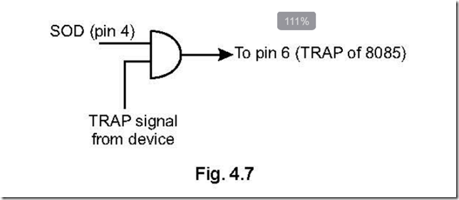
A manufacturer’s datasheet may provide guid­ ance regarding the dynamic resistance of a Zener diode in response to current, as previously shown in Figure 26-6. In practice, a packaged

voltage regulator such as the LM7805 would most likely be used instead of discrete compo­nents, since it includes self-calibrating features, requires no series resistor, and is relatively unaf­ fected by temperature. However, the LM7805 contains its own Zener diode, and the principle of operation is still the same.

AC Voltage Control and Signal Clipping

A more practical Zener application would be to limit AC voltage and/or impose clipping on an AC sinewave, using two diodes wired in series with opposed polarities. The basic schematic is shown in Figure 26-21, while clipping of the AC sinewave is illustrated in Figure 26-22. In this application, when one diode is reverse-biased, the other is forward-biased. A forward-biased Zener diode works like any other diode: it allows current to pass relatively freely, so long as the voltage ex­ceeds its threshold. When the AC current rever­ses, the Zeners trade their functions, so that the first one merely passes current while the second one limits the voltage. Thus, the diodes divert peak voltage away from the load. The Zener volt­ age of each diode would be chosen to be a small margin above the AC voltage for voltage control, and below the AC voltage for signal clipping.

clip_image049

Figure 26-21. Two Zener diodes placed in series, with op- posite polarities, can clip or limit the voltage sinewave of an AC signal.

Voltage Sensing

A Zener diode can be used to sense a small shift in voltage and provide a switched output in re­ sponse.

clip_image051

Figure 26-22. AC input showing a pure sinewave (left) and a clipped version (right) created by Zener diodes wired in series, as in the previous figure.

In Figure 26-23, the upper schematic shows a Zener diode preventing voltage from reaching the emitter of a PNP transistor while the divided input signal is below the Zener (breakdown) volt­ age of the diode. In this mode, the transistor is relatively non-conductive, very little current flows through it, and the output is now at near- zero voltage. As soon as the input signal rises above the Zener voltage, the transistor switches on and power is supplied to the output. The input is thus replicated in the output, as shown in the upper portion of Figure 26-24.

In Figure 26-23, the lower schematic shows aZener diode preventing voltage from reaching

the base of an NPN transistor while the input sig­nal is below the Zener (breakdown) voltage of the diode. In this mode, the transistor is relatively non-conductive, and power is supplied to the output. As soon as the input signal rises above

the Zener voltage, the transistor is activated, di­ verting the current to ground and bypassing the output, which is now at near-zero voltage. The input is thus inverted, as shown in the lower por­ tion of Figure 26-24 (provided there is enough current to drive the transistor into saturation).

clip_image053

Figure 26-23. A Zener diode can be used in conjunction with a PNP transistor. See text for details.


What Can Go Wrong

Overload

If maximum forward current is exceeded, the heat generated is likely to destroy the diode. If the diode is reverse-biased beyond its peak in­

clip_image055

Figure 26-24. Theoretical output from the transistors in the two previous schematics.

verse voltage limit, the current will overwhelm the diode’s ability to block it, and an avalanche breakdown will occur, once again probably de­ stroying the component. The graph in Figure 26-5 illustrates the performance range of a hypothetical generic diode.


Reversed Polarity

Zener diodes look almost identical to other types, and all diodes share the same convention of marking the cathode for identification. Yet Zeners must be reverse-biased while others are forward-biased. This creates a significant risk of installing a diode “the wrong way around,” with potentially destructive or at least confusing re­sults, especially when used in a power supply. The very low resistance of a diode to forward current makes it especially vulnerable to burnout if installed incorrectly.

Wrong Type of Diode

If a Zener diode is used accidentally where a sig­nal or rectifier diode is appropriate, the circuit will malfunction, as the Zener will probably have a much lower breakdown voltage, and therefore will not block reverse current. Conversely, if a sig­nal or rectifier diode is used where the circuit calls for a Zener diode, reverse voltage will be clam­ped (or regulated at the diode’s forward voltage value). Since diodes are often poorly marked, a sensible precaution is to store Zener diodes sep­arately from all other types.


field effect transistor What It Does,How It Works,Variants,Values,How to Use it and What Can Go Wrong

The term field-effect transistor encompasses a family primarily consisting of the junc­tion field-effect transistor (or JFET, which is the simplest generic type) and the metal-oxide semiconductor field-effect transistor (or MOSFET, also sometimes known as an insulated- gate field-effect transistor, or IGFET). Because the principles of operation overlap consid­erably, the entire -FET family is grouped in this entry.

What It Does

A field-effect transistor creates an electric field to control current flowing through a channel in a semiconductor. MOSFETs of microscopic size form the basis of complementary metal oxide semiconductor (CMOS) integrated circuit chips, while large discrete MOSFETs are capable of switching substantial currents, in lamp dimmers, audio amplifiers, and motor controllers. FETs have become indispensable in computer elec­tronics.

A bipolar transistor is generally thought of as a current amplifier because the current passing through it is controlled by a smaller amount of current passing through the base. By contrast, all FETs are considered to be voltage amplifiers, as the control voltage establishes field intensity, which requires little or no current. The negligible leakage through the gate of an FET makes it ideal for use in low-power applications such as portable hand-held devices.


How It Works

This section is divided into two subsections, de­ scribing the most widely used FETs: JFETs and MOSFETs.

JFETs

A junction field-effect transistor (or JFET) is the simplest form of FET. Just as a bipolar transistor can be of NPN or PNP type, a JFET can have an N- channel or Pchannel, depending whether the channel that transmits current through the de­ vice is negatively or positively doped. A detailed explanation of semiconductor doping will be found in the bipolar transistor entry.

Because negative charges have greater mobility, the N-channel type allows faster switching and is more commonly used than the P-channel type. A schematic symbol for it is shown in Figure 29-1 alongside the schematic for an NPN transistor. These symbols suggest the similarity of the de­ vices as amplifiers or switches, but it is important to remember that the FET is a primarily a voltage amplifier while the bipolar transistor is a current amplifier.
clip_image006

Figure 29-1. A comparison between schematic symbols for N-channel JFET (left) and NPN bipolar transistor (right) suggests their functional similarity as switches or amplifiers, although their behavior is markedly different.

Three JFETs are shown in Figure 29-2. The N- channel J112 type is supplied by several manu­facturers, the figure showing two samples, one from Fairchild Semiconductor (left) and the other from On Semiconductor (right). Although the full part numbers are different, the specifications are almost identical, including a drain-gate voltage of 35V, a drain-source voltage of 35V, and a gate current of 50mA. The metal-clad 2N4392 in the center has similar values but is three times the price, with a much higher power dissipation of 1.8W, compared with 300mW and 350mW for the other two transistors respectively.

clip_image008

Figure 29-2. Junction Field Effect Transistors (JFETs). See text for details.

Schematic symbols for N-channel and P-channel JFETs are shown in Figure 29-3, N-channel being on the left while P-channel is on the right. The upper-left and lower-left symbol variants are both widely used and are functionally identical. The upper-right and lower-right variants likewise

mean the same thing. Because the upper variants are symmetrical, an S should be added to clarify which terminal is the source. In practice, the S is often omitted, allowing some ambiguity. While the source and drain of some JFETs are in fact interchangeable, this does not apply to all types.

The circle around each symbol is occasionally omitted when representing discrete compo­nents, and is almost always omitted when mul­tiple FETs are shown connected to form an inte­ grated circuit.

clip_image010

Figure 29-3. Schematic symbols for junction field-effect transistors (JFETs). Left: N-channel. Right: P-channel. The symbols at top and bottom on each side are functionally identical. Circles may be omitted. Letter S may be omitted from the symmetrical symbol variants, even though this creates some ambiguity.

The internal function of an N-channel JFET is shown diagrammatically in Figure 29-4. In this component, the source terminal is a source of electrons, flowing relatively freely through the N- doped channel and emerging through the drain. Thus, conventional current flows nonintuitively from the drain terminal, to the source terminal, which will be of lower potential.

The JFET is like a normally-closed switch. It has a low resistance so long as the gate is at the same potential as the source. However, if the potential of the gate is reduced below the potential of the source—that is, the gate acquires a more rela­

tively negative voltage than the source—the cur­ rent flow is pinched off as a result of the field cre­ated by the gate. This is suggested by the lower diagram in Figure 29-4.

clip_image013

Figure 29-4. At top, conventional current flows freely from drain to source through the channel of an N-doped JFET. At bottom, the lowered voltage of the gate relative to the source creates a field effect that pinches off the flow of current.

The situation for a P-channel JFET is reversed, as shown in Figure 29-5. The source is now positive (but is still referred to as the source), while the drain can be grounded. Conventional current now flows freely from source to drain, so long as the gate is at the same positive potential as the source. If the gate voltage rises above the source voltage, the flow is pinched off.

A bipolar transistor tends to block current flow by default, but becomes less resistive when its base is forward-biased. Therefore it can be re­

clip_image015

Figure 29-5. At top, conventional current flows freely from source to drain through the channel of a P-doped JFET. At bottom, the higher voltage of the gate relative to the source creates a field effect that pinches off the flow of current.

ferred to as an enhancement device. By contrast, an N-channel JFET allows current to flow by de­ fault, and becomes more resistive when its base is reverse-biased, which widens the depletion lay­ er at the base junction. Consequently it can be referred to as a depletion device.

The primary characteristicts of a junction field- effect transistor relative to an NPN bipolar tran­sistor are summarized in the table in Figure 29-6.

JFET Behavior

The voltage difference between gate and source of a JFET is usually referred to as Vgs while the voltage difference between drain and source is referred to as Vds.

clip_image018

Figure 29-6. This table contrasts the characteristics of an N-channel JFET with those of an NPN bipolar transistor.

Suppose the gate of an N-channel JFET is con­nected with the source, so that Vgs=0. Now if Vds increases, the current flowing through the channel of the JFET also increases, approximately linearly with Vds. In other words, initially the JFET behaves like a low-value resistor in which the voltage across it, divided by the amperage flow­ ing through it, is approximately constant. This phase of the JFET’s behavior is known as its ohmic region. While the unbiased resistance of the channel in a JFET depends on the component type, it is generally somewhere between 10Ω and 1K.

If Vds increases still further, eventually no addi­tional flow of current occurs. At this point the channel has become saturated, and this plateau zone is referred to as the saturation region, often abbreviated Idss, meaning “the saturated drain current at zero bias.” Although this is a nearly constant value for any particular JFET, it may vary somewhat from one sample of a component to another, as a result of manufacturing variations.

If Vds continues to increase, the component fi­nally enters a breakdown state, sometimes re­ferred to by its full formal terminology as drain- source breakdown. The current passing through the JFET will now be limited only by capabilities

of the external power source. This breakdown state can be destructive to the component, and is comparable to the breakdown state of a typical diode.

What if the voltage at the gate is reduced below the voltage at the source—such as Vgs becomes negative? In its ohmic region, the component now behaves as if it has a higher resistance, and it will reach its saturation region at a lower cur­ rent value (although around the same value for Vds). Therefore, by reducing the voltage on the gate relative to the voltage at the source, the ef­ fective resistance of the component increases, and in fact it can behave as a voltage-controlled resistor.

The upper diagram in Figure 29-7 shows this graphically. Below it, the corresponding graph for a P-channel JFET looks almost identical, ex­cept that the current flow is reversed and is pinched off as the gate voltage rises above the source voltage. Also, the breakdown region is reached more quickly with a P-channel JFET than with an N-channel JFET.

MOSFETs

MOSFETs have become one of the most widely used components in electronics, everywhere from computer memory to high-amperage switching power supplies. The name is an acro­ nym for metal-oxide semiconductor field-effect transistor. A simplified cross-section of an N- channel MOSFET is shown in Figure 29-8.

Two MOSFETs are shown in Figure 29-9.

Like a JFET, a MOSFET has three terminals, iden­tified as drain, gate, and source, and it functions by creating a field effect that controls current flowing through a channel. (Some MOSFETS have a fourth terminal, described later). Howev­er, it has a metal source and drain making contact with each end of the channel (hence the term “metal” in its acronym) and also has a thin layer of silicon dioxide (hence the term “oxide” in its acronym) separating the gate from the channel, thus raising the impedance at the gate to at least

clip_image020

Figure 29-7. The top graph shows current passing through the channel of an N-channel JFET, depending on gate voltage and source voltage. The lower graph is for a P-channel JFET.

100,000 gigaohms and reducing gate current es­sentially to zero. The high gate impedance of a MOSFET allows it to be connected directly to the output of a digital integrated circuit. The layer of silicon dioxide is a dielectric, meaning that a field appled to one side creates an opposite field on the other side. The gate attached to the surface of the layer functions in the same way as one plate of a capacitor.

clip_image022

Figure 29-8. Simplified diagram of an N-channel MOS- FET. The thickness of the silicon dioxide layer has been greatly exaggerated for clarity. The black terminals are metallic.

clip_image024

Figure 29-9. Two MOSFETs. At left, the TO-220 package claims a drain current of up to 65A continuous, and a drain-to-source breakdown voltage 100V. At right, the smaller package offers a drain current of 175mA continuous, and a drain-to-source breakdown voltage of 300V.

The silicon dioxide also has the highly desirable property of insulating the gate from the channel, thus preventing unwanted reverse current. In a JFET, which lacks a dielectric layer, if source volt­ age is allowed to rise more than about 0.6V high­er than gate voltage, the direct internal connec­tion between gate and channel allows negative

charges to flow freely from source to gate, and as the internal resistance will be very low, the re­sulting current can be destructive. This is why the JFET must always be reverse-biased.

A MOSFET is freed from these restrictions, and the gate voltage can be higher or lower than the source voltage. This property enables an N- channel MOSFET to be designed not only as a depletion device, but alternatively as an en­ hancement device, which is “normally off” and can be switched on by being forward-biased. The primary difference is the extent to which the channel in the MOSFET is N-doped with charge carriers, and therefore will or will not conduct without some help from the gate bias.

In a depletion device, the channel conducts, but applying negative voltage to the gate can pinch off the current.

In an enhancement device, the channel does not conduct, but applying positive voltage to the gate can make it start to do so.

In either case, a shift of bias from negative to positive encourages channel conduction; the depletion and enhancement versions simply start from different points.

This is clarified in Figure 29-10. The vertical (log­ arithmic) scale suggests the current being con­ ducted through the channel of the MOSFET, while the green curve describes the behavior of a depletion version of the device. Where this curve crosses the center line representing 0 volts bias, the channel is naturally conductive, like a JFET. Moving left down the curve, as reverse bias is applied (shown on the horizontal axis), the component becomes less conductive until final­ ly its conductivity reaches zero.

Meanwhile on the same graph, the orange curve represents an enhancement MOSFET, which is nonconductive at 0 volts bias. As forward bias increases, the current also increases—similar to a bipolar transistor.

To make things more confusing, a MOSFET, like a JFET, can have a P-doped channel; and once

clip_image026

Figure 29-10. The current conduction of depletion and enhancement N-channel MOSFETs. See text for details. (Influenced by The Art of Electronics by Horowitz and Hill.)

again it can function in depletion or enhance­ ment mode. The behavior of this variant is shown in Figure 29-11. As before, the green curve shows the behavior of a depletion MOSFET, while the orange curve refers to the enhancement version. The horizontal axis now shows the voltage dif­ference between the gate and the drain terminal. The depletion component is naturally conduc­ tive at zero bias, until the gate voltage increases above the drain voltage, pinching off the current flow. The enhancement component is not con­ductive until reverse bias is applied.

Figure 29-12 shows schematic symbols that rep­ resent depletion MOSFETs. The two symbols on the left are functionally identical, representing N- channel versions, while the two symbols on the right represent P-channel versions. As in the case of JFETs, the letter “S” should be (but often is not) added to the symmetrical versions of the sym­bols, to clarify which is the source terminal. The left-pointing arrow identifies the components as N-channel, while in the symbols on the right, the right-pointing arrows indicate P-channel MOS­

clip_image028

Figure 29-11. The current conduction of depletion and enhancement P-channel MOSFETs. See text for details.

FETs. The gap between the two vertical lines in each symbol suggests the silicon dioxide dielec­tric. The right-hand vertical line represents the channel.

clip_image030

Figure 29-12. Schematic symbols for depletion MOS- FETs. These function similarly to JFETs. The two symbols on the left are functionally identical, and represent N- channel depletion MOSFETs. The two symbols on the right are both widely used to represent P-channel depletion MOSFETs.

For enhancement MOSFETs, a slightly different symbol uses a broken line between the source and drain (as shown in Figure 29-13) to remind

us that these components are “normally off” when zero-biased, instead of “normally on.” Here again a left-pointing arrow represents an N- channel MOSFET, while a right-pointing arrow represents a P-channel MOSFET.

clip_image032

Figure 29-13. Schematic symbols for enhancement MOSFETs. The two on the left are functionally identical, and represent N-channel enhancement MOSFETs. The two on the right represent P-channel enhancement MOS- FETs.

Because there is so much room for confusion re­ garding MOSFETs, a summary is presented in Figure 29-14 and Figure 29-15. In these figures, the relevant parts of each schematic symbol are shown disassembled alongside text explaining their meaning. Either of the symbols in Figure 29-14 can be superimposed on either of the symbols in Figure 29-15, to combine their functions. So, for instance, if the upper symbol in Figure 29-14 is superimposed on the lower sym­bol in Figure 29-15, we get an N-channel MOSFET of the enhancement type.

clip_image034

Figure 29-14. Either of the two symbols can be combined with either of the two symbols in the next figure, to create one of the four symbols for a MOSFET. See text for details.

clip_image036

Figure 29-15. Either of the two symbols can be combined with either of the two symbols from the previous figure, to create one of the four symbols for a MOSFET. See text for details.

In an additional attempt to clarify MOSFET be­ havior, four graphs are provided in Figure 29-16, Figure 29-17, Figure 29-18, and Figure 29-19. Like JFETs, MOSFETs have an initial ohmic region, fol­ lowed by a saturation region where current flows relatively freely through the device. The gate-to-

source voltage will determine how much flow is permitted. However, it is important to pay close attention to the graph scales, which differ for each of the four types of MOSFET.

clip_image038

Figure 29-16. Current flow through a depletion-type, N- channel MOSFET.

In all of these graphs, a bias voltage exists, which allows zero current to flow (represented by the graph line superimposed on the horizontal axis). In other words, the MOSFET can operate as a switch. The actual voltages where this occurs will vary with the particular component under con­ sideration.

The N-channel, enhancement-type MOSFET is especially useful as a switch because in its normally-off state (with zero bias) it presents a very high resistance to current flow. It requires a relatively low positive voltage at the gate, and effectively no gate current, to begin conducting conventional current from its drain terminal to its source terminal. Thus it can be driven directly by typical 5-volt logic chips.

Depletion-type MOSFETs are now less common­ ly used than the enhancement-type.

clip_image040

Figure 29-17. Current flow through a depletion-type, P- channel MOSFET.

clip_image044

Figure 29-18. Current flow through an enhancement- type, N-channel MOSFET.

clip_image042

Figure 29-19. Current flow through an enhancement- type, P-channel MOSFET.

The Substrate Connection

Up to this point, nothing has been said about a fourth connection available on many MOSFETs, known as the body terminal. This is connected to the substrate on which the rest of the compo­ nent is mounted, and acts as a diode junction with the channel. It is typically shorted to the source terminal, and in fact this is indicated by the schematic symbols that have been used so far. It is possible, however, to use the body ter­minal to shift the threshold gate voltage of the MOSFET, either by making the body terminal more negative than the source terminal (in an N- channel MOSFET) or more positive (in a P- channel MOSFET). Variants of the MOSFET sche­matic symbols showing the body terminal are shown in Figure 29-20 (for depletion MOSFETS) and Figure 29-21 (for enhancement MOSFETS).

A detailed discussion of the use of the body ter­minal to adjust characteristics of the gate is be­ yond the scope of this encyclopedia.

clip_image046

Figure 29-20. Schematic symbol variants for depletion MOSFETs, showing the body terminal separately accessible instead of being tied to the source terminal.

clip_image048

Figure 29-21. Schematic symbol variants for enhancement MOSFETs, showing the body terminal separately accessible instead of being tied to the source terminal.

Variants

A few FET variants exist in addition to the two previously discussed.

MESFET

The acronym stands for MEtal Semiconductor Field Effect Transistor. This FET variant is fabrica­ ted from gallium arsenide and is used primarily in radio frequency amplification, which is outside the scope of this encyclopedia.


V-Channel MOSFET

Whereas most FET devices are capable of han­dling only small currents, the Vchannel MOSFET (which is often abbreviated as a VMOS FET and has a V-shaped channel as its name implies) is capable of sustained currents of at least 50A and voltages as high as 1,000V. It is able to pass the high current because its channel resistance is well under 1Ω. These devices, commonly re­ ferred to as power MOSFETs, are available from all primary semiconductor manufacturers and are commonly used in switching power supplies.

Trench MOS

The TrenchMOS or Trenchgate MOS is a MOSFET variant that encourages current to flow vertically rather than horizontally, and includes other in­ novations that enable an even lower channel re­ sistance, allowing high currents with minimal heat generation. This device is finding applica­ tions in the automobile industry as a replace­ ment for electromechanical relays.

Values

The maximum values for JFETs, commonly found listed in datasheets, will specify Vds (the drain- source voltage, meaning the potential difference between drain and source); Vdg (the drain-gate voltage, meaning the potential difference be­ tween drain and gate); Vgsr (the reverse gate- source voltage); gate current; and total device dissipation in mW. Note that the voltage differ­ ences are relative, not absolute. Thus a voltage of 50V on the drain and 25V on the source might be acceptable in a component with a Vds of 25V. Similarly, while a JFET’s “pinch-off” effect begins as the gate becomes “more negative” than the source, this can be achieved if, for example, the source has a potential of 6V and the gate has a potential of 3V.

JFETs and MOSFETs designed for low-current switching applications have a typical channel re­ sistance of just a few ohms, and a maximum switching speed around 10Mhz.

The datasheet for a MOSFET will typically include values such as gate threshold voltage, which may be abbreviated Vgs (or Vth) and establishes the relative voltage at which the gate starts to play an active role; and the maximum on-state drain current, which may be abbreviated Id(on) and es­tablishes the maximum limiting current (usually at 25 degree Centigrade) between source and gate.

How to Use it

The combination of a very high gate impedance, very low noise, very low quiescent power con­sumption in its off state, and very fast switching capability makes the MOSFET suitable for many applications.

P-Channel Disadvantage

P-channel MOSFETs are generally less popular than N-channel MOSFETS because of the higher resistivity of P-type silicon, resulting from its low­er carrier mobility, putting it at a relative disad­ vantage.

Bipolar Substitution

In many instances, an appropriate enhancement-type MOSFET can be substituted for a bipolar transistor with better results (lower noise, faster action, much higher impedance, and probably less power dissipation).

Amplifier Front Ends

While MOSFETs are well-suited for use in the front end of an audio amplifier, chips containing MOS­ FETs are now available for this specific purpose.

Voltage-Controlled Resistor

A simple voltage-controlled resistor can be built around a JFET or MOSFET, so long as its perfor­mance remains limited to the linear or ohmic re­ gion.

Compatibility with Digital Devices

 A JFET may commonly use power supplies in the range of 25VDC. However, it can accept the high/

low output from a 5V digital device to control its gate. A 4.7K pullup resistor is an appropriate val­ue to be used if the FET is to be used in conjunc­tion with a TTL digital chip that may have a volt­ age swing of only approximately 2.5V between its low and high thresholds.

What Can Go Wrong
Static Electricity

Because the gate of a MOSFET is insulated from the rest of the component, and functions much like a plate of a capacitor, it is especially likely to accumulate static electricity. This static charge may then discharge itself into the body of the component, destroying it. A MOSFET is particu­larly vulnerable to electrostatic discharge be­ cause its oxide layer is so thin. Special care should be taken either when handling the component, or when it is in use. Always touch a grounded object or wear a grounded wrist band when han­dling MOSFETs, and be sure that any circuit using MOSFETs includes appropriate protection from static and voltage spikes.

A MOSFET should not be inserted or removed while the circuit in which it performs is switched on or contains residual voltage from undis ­charged capacitors.

Heat

Failure because of overheating is of special con­cern when using power MOSFETs. A Vishay Ap­ plication Note (“Current Power Rating of Power Semiconductors”) suggests that this kind of com­ponent is unlikely to operate at less than 90 de­ grees Centigrade in real-world conditions, yet the power handling capability listed in a data­ sheet usually assumes an industry standard of 25 degrees Centigrade.

On the other hand, ratings for continuous power are of little relevance to switching devices that have duty cycles well below 100%. Other factors also play a part, such as the possibility of power surges, the switching frequency, and the integ­rity of the connection between the component

and its heat sink. The heat sink itself creates un­ certainty by tending to average the temperature of the component, and of course there is no sim­ple way to know the actual junction temperature, moment by moment, inside a MOSFET.

Bearing in mind the accumulation of unknown factors, power MOSFETs should be chosen on an extremely conservative basis. According to a tu­torial in the EE Times, actual current switched by a MOSFET should be less than half of its rated current at 25 degrees, while one-fourth to one- third are common. Figure 29-22 shows the real- world recommended maximum drain current at various temperatures. Exceeding this recommendation can create additional heat, which cannot be dissipated, leading to further accu­mulation of heat, and a thermal runaway condi­ tion, causing eventual failure of the component.

clip_image052

Figure 29-22. Maximum advised drain current through a power MOSFET, related to case temperature of the component. Derived from EE Times Power MOSFET Tutorial.


Wrong Bias

As previously noted, applying forward bias to a JFET can result in the junction between the gate and the source starting to behave like a forward- biased diode, when the voltage at the gate is greater than the voltage at the source by ap­proximately 0.6V or more (in an N-channel JFET). The junction will present relatively little resist­ance, encouraging excessive current and de­ structive consequences. It is important to design devices that allow user input in such a way that user error can never result in this eventuality.


bipolar transistor What It Does,How It Works,Variants,Values,How to Use it and What Can Go Wrong

The word transistor, on its own, is often used to mean bipolar transistor, as this was the type that became most widely used in the field of discrete semiconductors. However, bipolar transistor is the correct term. It is sometimes referred to as a bipolar junction transistor or BJT.

What It Does

A bipolar transistor amplifies fluctuations in cur­ rent or can be used to switch current on and off. In its amplifying mode, it replaced the vacuum tubes that were formerly used in the amplifica­tion of audio signals and many other applica­tions. In its switching mode it resembles a re­ lay, although in its “off” state the transistor still allows a very small amount of current flow, known as leakage.

A bipolar transistor is described as a discrete semiconductor device when it is individually packaged, with three leads or contacts. A pack­ age containing multiple transistors is an integra­ted circuit. A Darlington pair actually contains two transistors, but is included here as a discrete component because it is packaged similarly and functions like a single transistor. Most integrated circuits will be found in Volume 2 of this ency­clopedia.


How It Works

Although the earliest transistors were fabricated from germanium, silicon has become the most commonly used material. Silicon behaves like an insulator, in its pure state at room temperature, but can be “doped” (carefully contaminated) with impurities that introduce a surplus of elec­trons unbonded from individual atoms. The re­sult is an N-type semiconductor that can be in­ duced to allow the movement of electrons through it, if it is biased with an external voltage. Forward bias means the application of a positive voltage, while reverse bias means reversing that voltage.

Other dopants can create a deficit of electrons, which can be thought of as a surplus of “holes” that can be filled by electrons. The result is a P– type semiconductor.

A bipolar NPN transistor consists of a thin central P-type layer sandwiched between two thicker N- type layers. The three layers are referred to as collector, base, and emitter, with a wire or contact

attached to each of them. When a negative charge is applied to the emitter, electrons are forced by mutual repulsion toward the central base layer. If a forward bias (positive potential) is applied to the base, electrons will tend to be at­ tracted out through the base. However, because the base layer is so thin, the electrons are now close to the collector. If the base voltage increa­ ses, the additional energy encourages the elec­trons to jump into the collector, from which they will make their way to the positive current source, which can be thought of as having an even great­ er deficit of electrons.

Thus, the emitter of an NPN bipolar transistor emits electrons into the transistor, while the col­ lector collects them from the base and moves them out of the transistor. It is important to re­ member that since electrons carry a negative charge, the flow of electrons moves from nega­tive to positive. The concept of positive-to- negative current is a fiction that exists only for historical reasons. Nevertheless, the arrow in a transistor schematic symbol points in the direc­tion of conventional (positive-to-negative) cur­ rent.

In a PNP transistor, a thin N-type layer is sand­ wiched between two thicker P-type layers, the base is negatively biased relative to the emitter, and the function of an NPN transistor is reversed, as the terms “emitter” and “collector” now refer to the movement of electron-holes rather than electrons. The collector is negative relative to the base, and the resulting positive-to-negative cur­ rent flow moves from emitter to base to collector. The arrow in the schematic symbol for a PNP transistor still indicates the direction of positive current flow.

Symbols for NPN and PNP transistors are shown in Figure 28-1. The most common symbol for an NPN transistor is shown at top-left, with letters C, B, and E identifying collector, base, and emitter. In some schematics the circle in the symbols is omitted, as at top-right.

A PNP transistor is shown in the center. This is the most common orientation of the symbol, since its collector must be at a lower potential than its emitter, and ground (negative) is usually at the bottom of a schematic. At bottom, the PNP sym­bol is inverted, allowing the positions of emitter and collector to remain the same as in the symbol for the NPN transistor at the top. Other orienta­tions of transistor symbols are often found, mere­ ly to facilitate simpler schematics with fewer con­ductor crossovers. The direction of the arrow in the symbol (pointing out or pointing in) always differentiates NPN from PNP transistors, respec­tively, and indicates current flowing from posi­tive to negative.

clip_image006

Figure 28-1. Symbols for an NPN transistor (top) and a PNP transistor (center and bottom). Depending on the schematic in which the symbol appears, it may be rotated or inverted. The circle may be omitted, but the function of the component remains the same.

NPN transistors are much more commonly used than PNP transistors. The PNP type was more dif­ficult and expensive to manufacture initially, and

circuit design evolved around the NPN type. In addition, NPN transistors enable faster switch­ing, because electrons have greater mobility than electron-holes.

To remember the functions of the collector and the emitter in an NPN transistor, you may prefer to think in terms of the collector collecting pos­itive current into the transistor, and the emitter emitting positive current out of the transistor. To remember that the emitter is always the terminal with an arrow attached to it (both in NPN and PNP schematic symbols), consider that “emitter” and “arrow” both begin with a vowel, while “base” and “collector” begin with consonants. To remember that an NPN transistor symbol has its arrow pointing outward, you can use the mnemonic “N/ever P/ointing i/N.”

Current flow for NPN and PNP transistors is illus­trated in Figure 28-2. At top-left, an NPN transis­tor passes no current (other than a small amount of leakage) from its collector to its emitter so long as its base is held at, or near, the potential of its emitter, which in this case is tied to negative or ground. At bottom-left, the purple positive sym­bol indicates that the base is now being held at a relatively positive voltage, at least 0.6 volts higher than the emitter (for a silicon-based tran­sistor). This enables electrons to move from the emitter to the collector, in the direction of the blue arrows, while the red arrows indicate the conventional concept of current flowing from positive to negative. The smaller arrows indicate a smaller flow of current. A resistor is included to protect the transistor from excessive current, and can be thought of as the load in these circuits.

At top-right, a PNP transistor passes no current (other than a small amount of leakage) from its emitter to its collector so long as its base is held at, or near, the potential of the emitter, which in this case is tied to the positive power supply. At bottom-right, the purple negative symbol indi­cates that the base is now being held at a rela­ tively negative voltage, at least 0.6 volts lower than the emitter. This enables electrons and cur­ rent to flow as shown. Note that current flows

into the base in the NPN transistor, but out from the base in the PNP transistor, to enable conduc­tivity. In both diagrams, the resistor that would normally be included to protect the base has been omitted for the sake of simplicity.

clip_image009

Figure 28-2. Current flow through NPN and PNP transistors. See text for details.

An NPN transistor amplifies its base current only so long as the positive potential applied to the collector is greater than the potential applied to the base, and the potential at the base must be greater than the potential at the emitter by at least 0.6 volts. So long as the transistor is biased in this way, and so long as the current values re­ main within the manufacturer’s specified limits, a small fluctuation in current applied to the base will induce a much larger fluctuation in current between the collector and the emitter. This is why a transistor may be described as a current amplifier.

A voltage divider is often used to control the base potential and ensure that it remains less than the potential on the collector and greater than the potential at the emitter (in an NPN transistor). See Figure 28-3.

See Chapter 10 for additional information about the function of a voltage divider.

clip_image012

Figure 28-3. Resistors R1 and R2 establish a voltage divider to apply acceptable bias to the base of an NPN transistor.

Current Gain

The amplification of current by a transistor is known as its current gain or beta value, which can be expressed as the ratio of an increase in col­ lector current divided by the increase in base current that enables it. Greek letter β is customarily used to represent this ratio. The formula looks like this:

β = ΔIc / ΔIb

where Ic is the collector current and Ib is the base current, and the Δ symbol represents a small change in the value of the variable that follows it.

Current gain is also represented by the term hFE, where E is for the common Emitter, F is for For­ ward current, and lowercase letter h refers to the transistor as a “hybrid” device.

The beta value will always be greater than 1 and is often around 100, although it will vary from one type of transistor to another. It will also be affected by temperature, voltage applied to the transistor, collector current, and manufacturing inaccuracies. When the transistor is used outside of its design parameters, the formula to deter­ mine the beta value no longer directly applies.

There are only two connections at which current can enter an NPN transistor and one connection where it can leave. Therefore, if Ie is the current from the emitter, Ic is the current entering the collector, and Ib is the current entering the base:

Ie = Ic + Ib

If the potential applied to the base of an NPN transistor diminishes to the point where it is less than 0.6V above the potential at the emitter, the transistor will not conduct, and is in an “off” state, although a very small amount of leakage from collector to emitter will still occur.

When the current flowing into the base of the transistor rises to the point where the transistor cannot amplify the current any further, it be­ comes saturated, at which point its internal impedance has fallen to a minimal value. Theoreti­cally this will allow a large flow of current; in practice, the transistor should be protected by resistors from being damaged by high current resulting from saturation.

Any transistor has maximum values for the col­ lector current, base current, and the potential

difference between collector and emitter. These values should be provided in a datasheet. Ex­ceeding them is likely to damage the compo­ nent.

Terminology

In its saturated mode, a transistor’s base is satu­ rated with electrons (with no room for more) and the internal impedance between collector and emitter drops as low as it can go.

The cutoff mode of an NPN transistor is the state where a low base voltage eliminates all current flow from collector to emitter other than a small amount of leakage.

The active mode, or linear mode, is the intermedi­ ate condition between cutoff and saturated, where the beta value or hFE (ratio of collector current to base current) remains approximately constant. That is, the collector current is almost linearly proportional to the base current. This lin­ ear relationship breaks down when the transistor nears its saturation point.

Variants

Small signal transistors are defined as having a maximum collector current of 500 mA and max­ imum collector power dissipation of 1 watt. They can be used for audio amplification of low-level inputs and for switching of small currents. When determining whether a small-signal transistor can control an inductive load such as a motor or relay coil, bear in mind that the initial current surge will be greater than the rated current draw during sustained operation.

Small switching transistors have some overlap in specification with small signal transistors, but generally have a faster response time, lower beta value, and may be more limited in their tolerance for collector current. Check the manufacturer’s datasheet for details.

High frequency transistors are primarily used in video amplifiers and oscillators, are physically small, and have a maximum frequency rating as high as 2,000 MHz.

Power transistors are defined as being capable of handling at least 1 watt, with upper limits that can be as high as 500 watts and 150 amps. They are physically larger than the other types, and may be used in the output stages of audio am­plifiers, and in switching power supplies (see Chapter 16). Typically they have a much lower current gain than smaller transistors (20 or 30 as opposed to 100 or more).

Sample transistors are shown in Figure 28-4. Top: A 2N3055 NPN power transistor. This type was originally introduced in the late 1960s, and ver­sions are still being manufactured. It is often found in power supplies and in push-pull power amplifiers, and has a total power dissipation rat­ ing of 115W. Second row, far left: general purpose switching-amplification PNP power transistor rated for up to 50W power dissipation. Second row, far right: A high-frequency switching tran­ sistor for use in lighting ballast, converters, in­verters, switching regulators, and motor control systems. It tolerates relatively high voltages (up to 700V collector-emitter peak) and is rated for up to 80W total power dissipation. Second row, center-left and center-right: Two variants of the 2N2222 NPN small signal switching transistor, first introduced in the 1960s, and still very widely used. The metal can is the TO-19 package, capa­ble of slightly higher power dissipation than the cheaper plastic TO-92 package (1.8W vs. 1.5W with a collector temperature no greater than 25 degrees Centigrade).

Packaging

Traditionally, small-signal transistors were pack­ aged in small aluminum “cans” about 1/4” in di­ameter, and are still sometimes found in this form. More commonly they are embedded in buds of black plastic. Power transistors are pack­ aged either in a rectangular module of black

clip_image015

Figure 28-4. Samples of commonly used transistors. See text for details.

plastic with a metal back, or in a round metal “button.” Both of these forms are designed to dissipate heat by being screw-clamped to a heat sink.

Connections

Often a transistor package provides no clue as to which lead is the emitter, which lead is the base, and which lead is the collector. Old can-style packaging includes a protruding tab that usually points toward the emitter, but not always. Where power transistors are packaged in a metal enclo­sure, it is typically connected internally with the collector. In the case of surface-mount transis­ tors, look for a dot or marker that should identify the base of a bipolar transistor or the gate of a field-effect transistor.

A through-hole transistor usually has its part number printed or engraved on its package, al­

though a magnifying glass may be necessary to see this. The component’s datasheet may then be checked online. If a datasheet is unavailable, meter-testing will be necessary to confirm the functions of the three transistor leads. Some mul­timeters include a transistor-test function, which may validate the functionality of a transistor while also displaying its beta value. Otherwise, a meter can be put in diode-testing mode, and an unpowered NPN transistor should behave as if diodes are connected between its leads as shown in Figure 28-5. Where the identities of the transistor’s leads are unknown, this test will be sufficient to identify the base, after which the collector and emitter may be determined empir­ically by testing the transistor in a simple low- voltage circuit such as that shown in Figure 28-6.

clip_image017

Figure 28-5. An NPN transistor can behave as if it contains two diodes connected as shown. Where the functions of the leads of the transistor are unknown, the base can be identified by testing for conductivity.

How to Use it

The following abbreviations and acronyms are common in transistor datasheets. Some or all of the letters following the initial letter are usually, but not always, formatted as subscripts:

hFE

Forward current gain

β

Same as hFE

VCEO

Voltage between collector and emitter (no

connection at base)

clip_image019ICM IBM PTOT

TJ

Maximum peak current at collector Maximum peak current at base

Total maximum power dissipation at room temperature

Maximum junction temperature to avoid damage

Figure 28-6. This simple schematic can be used to breadboard-test a transistor empirically, determining its functionality and the identities of its collector and emitter leads.

VCBO

Voltage between collector and base (no con­

nection at emitter)

VEBO

Voltage between emitter and base (no con­

nection at collector)

VCE sat

Saturation voltage between collector and

emitter

VB ,Esat

Saturation voltage between base and emit­

ter

Ic

Current measured at collector

Often these terms are used to define “absolute maximum values” for a component. If these max­ imums are exceeded, damage may occur.

A manufacturer’s datasheet may include a graph showing the safe operating area (SOA) for a tran­sistor. This is more common where power tran­sistors are involved, as heat becomes more of an issue. The graph in Figure 28-7 has been adapted from a datasheet for a silicon diffused power transistor manufactured by Philips. The safe op­erating area is bounded at the top by a horizontal segment representing the maximum safe cur­ rent, and at the right by a vertical segment rep­ resenting the maximum safe voltage. However, the rectangular area enclosed by these lines is reduced by two diagonal segments representing the total power limit and the second breakdown limit. The latter refers to the tendency of a tran­sistor to develop internal localized “hot spots” that tend to conduct more current, which makes them hotter, and able to conduct better—ulti­mately melting the silicon and causing a short circuit. The total power limit and the second breakdown limit reduce the safe operating area, which would otherwise be defined purely by maximum safe current and maximum safe volt­ age.

Uses for discrete transistors began to diminish when integrated circuits became cheaper and started to subsume multi-transistor circuits. For instance, an entire 5-watt audio amplifier, which used to be constructed from multiple compo­nents can now be bought on a chip, requiring just

clip_image021

Figure 28-7. Adapted from a Philips datasheet for a power transistor, this graph defines a safe operating area (SOA) for the component. See text for details.

a few external capacitors. More powerful audio equipment typically uses integrated circuits to process inputs, but will use individual power transistors to handle high-wattage output.

Darlington Pairs

Discrete transistors are useful in situations where current amplification or switching is required at just one location in a circuit. An example would be where one output pin from a microcontrol­ler must switch a small motor on and off. The motor may run on the same voltage as the mi­crocontroller, but requires considerably more current than the typical 20mA maximum avail­ able from a microcontroller output. A Darlington pair of transistors may be used in this application. The overall gain of the pair can be 100,000 or more. See Figure 28-8. If a power source feeding

through a potentiometer is substituted for the microcontroller chip, the circuit can function as a motor speed control (assuming that a generic DC motor is being used).

In the application shown here, the microcontrol­ler chip must share a common ground (not shown) with the transistors. The optional resistor may be necessary to prevent leakage from the first transistor (when in its “off” state) from trig­ gering the second. The diode protects the tran­sistors from voltage transients that are likely when the motor stops and starts.

clip_image023

Figure 28-8. Where the emitter of one NPN transistor is coupled to the base of another, they form a Darlington pair (identified by the dashed rectangle in this schemat- ic). Multiplying the gain of the first transistor by the gain of the second gives the total gain of the pair.

A Darlington pair can be obtained in a single transistor-like package, and may be represented by the schematic symbol shown in Figure 28-9.

Various through-hole Darlington packages are shown in Figure 28-10.

clip_image025

Figure 28-9. When a Darlington pair is embedded in a single transistor-like package, it may be represented by this schematic symbol. The leads attached to the package can be used as if they are the emitter, base, and collector of a single NPN transistor.

clip_image027

Figure 28-10. Various packaging options for Darlington pairs. From left to right: The 2N6426 contains a Darling- ton pair rated to pass up to 500mA continuous collector current. The 2N6043 is rated for 8A continuous. The ULN2003 and ULN2083 chips contain seven and eight Darlington pairs, respectively.

Seven or eight Darlington pairs can be obtained in a single integrated chip. Each transistor pair in these chips is typically rated at 500mA, but they can be connected in parallel to allow higher cur­ rents. The chip usually includes protection di­ odes to allow it to drive inductive loads directly.

A typical schematic is shown in Figure 28-11. In this figure, the microcontroller connections are hypothetical and do not correspond with any ac­ tual chip. The Darlington chip is a ULN2003 or similar, containing seven transistor pairs, each with an “input” pin on the left and an “output”

pin opposite it on the right. Any of pins 1 through 7 down the left side of the chip can be used to control a device connected to a pin on the op­ posite side.

A high input can be thought of as creating a neg­ ative output, although in reality the transistors inside the chip are sinking current via an external device—a motor, in this example. The device can have its own positive supply voltage, shown here as 12VDC, but must share a common ground with the microcontroller, or with any other compo­ nent which is being used on the input side. The lower-right pin of the chip shares the 12VDC sup­ ply because this pin is attached internally to clamp diodes (one for each Darlington pair), which protect against surges caused by induc­ tive loads. For this reason, the motor does not have a clamp diode around it in the schematic.

The Darlington chip does not have a separate pin for connection with positive supply voltage, be­ cause the transistors inside it are sinking power from the devices attached to it.

clip_image029

Figure 28-11. A chip such as the ULN2003 contains sev- en Darlington pairs. It will sink current from the device it is driving. See text for details.

A surface-mount Darlington pair is shown in

Figure 28-12. This measures just slightly more

than 0.1” long but is still rated for up to 500mA collector current or 250mW total power dissipa­tion (at a component temperature no higher than 25 degrees Centigrade).

clip_image031

Figure 28-12. A surface-mount package for a Darlington pair. Each square in the background grid measures 0.1”. See text for additional details.

Amplifiers

Two basic types of transistor amplifiers are shown in Figure 28-13 and Figure 28-14. The common-collector configuration has current gain but no voltage gain. The capacitor on the input side blocks DC current from entering the ampli­fier circuit, and the two resistors forming a volt­ age divider on the base of the transistor establish a voltage midpoint (known as the quiescent point or operating point) from which the signal to be amplified may deviate above and below.

The common-emitter amplifier provides voltage gain instead of current gain, but inverts the phase of the input signal. Additional discussion of amplifier design is outside the scope of this encyclopedia.

In switching applications, modern transistors have been developed to handle a lot of current compared with earlier versions, but still have some limitations. Few power transistors can han­ dle more than 50A flowing from collector to emitter, and 1,000V is typically a maximum value. Electromechanical relays continue to exist be­ cause they retain some advantages, as shown in the table in Figure 28-15, which compares switching capabilities of transistors, solid-state relays, and electromechanical relays.

clip_image033

Figure 28-13. The basic schematic for a common- collector amplifier. See text for details.

clip_image035

Figure 28-14. The basic schematic for a common-emitter amplifier. See text for details.

clip_image037

Figure 28-15. A comparison of characteristics of switching devices.

What Can Go Wrong
Wrong Connections on a Bipolar Transistor

Failing to identify a transistor’s leads or contacts correctly can obviously be a potential source of damage, but swapping the collector and emitter

accidentally will not necessarily destroy the tran­sistor. Because of the inherent symmetry of the device, it will in fact function with collector and emitter connections reversed. Rohm, a large semiconductor manufacturer, has included this scenario in its general information pages and concludes that the primary indicator of trans­ posed connections is that the β value, or hFE , drops to about 1/10th of specification. If you are using a transistor that works but provides much less amplification than you expect, check that the emitter and collector leads are not transposed.

Wrong Connections on a Darlington Pair Chip

While a single-component package for a Dar­lington pair functions almost indistinguishably from a single transistor, multiple Darlington pairs in a DIP package may create confusion because the component behaves differently from most other chips, such as logic chips.

A frequent error is to ground the output device instead of applying positive power to it. See Figure 28-11 and imagine an erroneous connec­tion of negative power instead of the 12VDC pos­ itive power.

Additional confusion may be caused by reading a manufacturer’s datasheet for a Darlington pair chip such as the ULN2003. The datasheet depicts the internal function of the chip as if it contains logic inverters. While the chip can be imagined as behaving this way, in fact it contains bipolar transistors that amplify the current applied to the base of each pair. The datasheet also typically will not show the positive connection that should be made to the common-diode pin (usually at bottom-right), to provide protection from surges caused by inductive loads. This pin must be dis­

tinguished carefully from the common-ground

pin (usually at bottom-left). The positive connec­tion to the common-diode pin is optional; the common-ground connection is mandatory.
Soldering Damage

Like any semiconductor, transistors are vulnera­ble to heat and can be damaged while soldering, although this seldom happens if a low-wattage iron is used. A copper alligator clip can be applied as a heat sink to each lead before it is soldered.

Excessive Current or Voltage

During use, a transistor will be damaged if it is subjected to current or voltage outside of its rat­ed range. Passing current through a transistor without any series resistance to protect it will al­ most certainly burn it out, and the same thing can happen if incorrect resistor values are used.

The maximum wattage that a transistor can dis­sipate will be shown in its datasheet. Suppose, for example, this figure is 200mW, and you are using a 12VDC supply. Ignoring the base current, the maximum collector current will be 200 / 12 = approximately 15mA. If the transistor’s emitter is connected to ground, and the load applied to the transistor output has a high impedance, and if we ignore the transresistance, Ohm’s Law sug­gests that a resistor that you place between the collector and the supply voltage should have a resistance of at least 12 / 0.015 = 800 ohms.

When transistors are used in switching applica­tions, it is customary for the base current to be 1/5th of the collector current. In the example dis­ cussed here, a 4.7K resistor might be appropriate. A meter should be used to verify actual current and voltage values.

Excessive Leakage

In a Darlington pair, or any other configuration where the output from one transistor is connec­ted with the base of another, leakage from the first transistor while in its “off” state can be am­ plified by the second transistor. If this is unac­ceptable, a bypass resistor can be used to divert some of the leakage from the base of the second transistor to ground. Of course the resistor will also steal some of the base current when the first transistor is active, but the resistor value is typi­cally chosen so that it takes no more than 10% of the active current. See Figure 28-8 for an example of a bypass resistor added to a Darlington pair.