Using the ports

Introduction

The first pattern in this chapter (PORT I / O [page 174]) is concerned with basic soft- ware techniques for interacting with the digital ports on an 8051 microcontroller.

The second pattern (PORT HEADER [page 184]) encapsulates a design guideline that helps you cope with the fact that many different components in a larger project will each require port access: specifically, PORT HEADER demonstrates how the port access for the whole project can be integrated into a single file. Use of these techniques can ease project development, maintenance and porting.

The following points should also be noted:

● This chapter does not consider the hardware that will be connected to the port: see Chapters 7 and 8 for relevant hardware details.

● This chapter does not consider analog input and output: for this, see Part G.


A rudimentary software architecture:Project header

Project header
Context

● You are developing an embedded application using one or more members of the 8051 family of microcontrollers.

● You are designing an appropriate software foundation for your application.

Problem

How do you group together all the information relating to the hardware platform used in your project?

Background

Solution

As we saw in Chapter 3, the 8051 family shares a common set of core facilities. However, it is a family – rather than a group of clones – and the different family members have different features and facilities. For example, some devices require 12 oscillator cycles per instruction, while others perform the same instruction in 6, 4 or even 1 oscillator cycle (see Chapters 3 and 4).

If you create an application using a particular 8051 device operating at a particular oscillator frequency, this information will be required when compiling many of the different source files in your project. This information will also be required by anyone who wishes to use your code.

The ‘Project Header’ is simply a header file, included in all projects, that groups all of this information in one place. As such, it is a practical implementation of a stan- dard software design guideline: ‘Do not duplicate information in numerous files; place the common information in a single file, and refer to it where necessary.’

In the case of the great majority of the examples in this book, we use a Project Header file. This is always called Main.H. An example of a typical project header file is included in Listing 9.7. Please note that this is a real example and not all of the features of this file have yet been considered in this book.

A rudimentary software  architecture-0167A rudimentary software  architecture-0168A rudimentary software  architecture-0169

Hardware resource implications

There are no hardware resource implications.

Reliability and safety implications

Use of P ROJECT H EADER can help to improve reliability, not least because it helps to make your code more readable, because anyone using your projects knows where to find key information, such as the model of microcontroller and the oscillator frequency.

Use of P ROJECT H EADER can help to improve the reliability of applications which are subsequently ported to a different microcontroller, as discussed in the remainder of this chapter.

Portability

The use of a project header can help to make your code more easily portable, by plac- ing some of the key rnicrocontroller-dependent data in one place.

In addition, the typedef statements in the file create three key user-defined types which are used in all of the projects in this book:

typedef unsigned char tByte; typedef unsigned int tWord; typedef unsigned long tLong;

Thus, in the projects you will see code like this:

tWord Temperature;

Rather than:

unsigned int Temperature;

If the code is ported into – say – a 16-bit environment, changes to only three typedef statements are required in order to adapt the variable sizes to a new com- piler. Without the use of these user-defined types, porting the code becomes more complicated and error prone.

Overall strengths and weaknesses

clip_image003PROJECT HEADER can help to make your code more readable, not least because anyone using your projects knows where to find key information, such as the model of microcontroller and the oscillator frequency.

PROJECT HEADER can help to make your code more easily portable.

Related patterns and alternative solutions

See PORT HEADER [page 184].

Examples

Almost every example project on the CD includes a project header file. Search for the file Main.H.

Further reading


A rudimentary software architecture

Introduction

In the first pattern in this chapter we consider the minimum software environment required to create a typical embedded application: this environment is called SUPER LOOP [page 162].

Please note that we will use Super Loop in this book primarily to allow us to illus- trate some introductory software patterns in Chapters 10, 11 and 12. In Chapter 13 we will demonstrate that a co-operative scheduler provides a more appropriate environment than a SUPER LOOP for the great majority of embedded applications.

The second pattern (PROJECT HEADER [page 169) is a practical implementation of a standard software design guideline: ‘Do not duplicate information in numerous files; place the common information in a single file and refer to it where necessary.’ Specifically, PROJECT HEADER pulls together the information connected with the par- ticular microcontroller used in your application, along with other key pieces of information that are required by many of the files in your project.


SSR DRIVER (AC)

SSR DRIVER (AC)
Context

● You are developing an embedded application using one or more members of the 8051 family of microcontrollers.

● You are designing an appropriate hardware foundation for your application.

Problem

How do you ‘switch on’ or ‘switch off’ a piece of mains-powered (AC) electrical equip- ment using a microcontroller?

Background

We introduce DC SSRs in SSR DRIVER ( DC ) [page 144]. Please refer to the previous pattern for general background information on SSRs.

The main differences between the two devices is that, while in DC SSRs, the output stage typically consists of a MOSFET, in AC SSRs, the output stage is usually a TRIAC. Very briefly, a TRIAC is a semiconductor switch that allows current to flow in both directions: this is, of course, precisely what we require with AC loads.

Solution

Use of SSRs is generally straightforward: the inputs are directly compatible with microcontroller port values, and – because of the built-in opto-isolation – there is gen- erally no need to add additional gates between the microcontroller and the SSR. The examples that follow will illustrate the use of these devices.

Pull-up resistors

When using this pattern, you may need to incorporate pull-up resistors in your hard- ware design. See NAKED LED [page 110] for further details.

Reliability and safety issues

See the start of this chapter for general reliability and safety issues.

See also SSR DRIVER ( DC ) [page 144] for basic SSR guidelines.

A key difference between AC and DC SSRs is that, while MOSFETs have very low losses, the TRIAC output stages used in AC SSRs typically have a voltage drop of up to 1.5V when they conduct: this translates directly into a power loss of up to 1.5W per Ampere of current. If using a high-power device (greater than around 4A), you will require a heat sink.

When you fit a heat sink, keep it isolated from the case of your application. Never

bolt it to the chassis: this can have deadly consequences.

Portability

SSRs can be used with any processor type. However, there are other portability issues to consider.

The most important (already briefly mentioned) is that an AC SSR cannot be used to switch DC. The reason for this is that the AC SSR contains zero-crossing detection circuits. Because the DC supply never crosses zero, the SSR will never switch on.

Similarly, most DC SSRs are based on MOSFETs. Using a MOSFET to switch AC is ineffective: at best, the device will act as a form of rectifier for a short period, until it overheats.

Overall strengths and weaknesses

SSRs do not exhibit switch bounce. SSRs do not wear out (in normal use). SSRs do not generate acoustic noise.

Many (AC) SSRs incorporate ‘zero-crossing detection’ circuits. This helps to greatly reduce EM emissions.

SSRs are resistant to shock and vibration. SSRs have a high switching speed.

SSRs have high levels of isolation between the ‘control’ and ‘switching’ circuits.

EM relays can usually switch higher voltages and currents.

The on-resistance of AC SSRs is much larger than EM relays. This means extra heat is generated and you must plan for a heat sink or other forms of cooling.

Unlike an EM relay, the ‘switch’ in the AC SSR (usually a TRIAC) exhibits some leakage current in the off-state.

Most AC SSRs will not switch DC, partly because of the zero-crossing detection. SSRs can be irrevocably damaged almost instantly by excessive voltage and / or

current: EM relays are more forgiving.

The typical failure mode of an SSR is an output short circuit: this can be dangerous.

The ‘switched’ side has a minimum operating voltage and current: these may be quite high, which can make it more difficult to perform initial tests on small-scale prototypes.

Related patterns and alternative solutions

See the other patterns in this chapter and Chapter 7 for alternative approaches.

Example: Controlling a central-heating pump with an SSR

In EMR DRIVER [page 149] we present an example of a small reed relay used to control a central-heating pump. Here we consider an alternative solution using an AC SSR.

Recall that the pump we wish to control was a Grundfos Selectric UPS 15-50: this required 240V AC (50 Hz), and 0.17–0.42A. In this case, we will use a Crydom MP240D3 SSR. This is suitable for direct interfacing to a microcontroller and has a current capacity of 3A continuous (80A surge) at up to 280V AC. Figure 8.8 shows a suitable circuit.

Driving AC loads-0160

Overall, control of central heating in this manner is probably best carried out using an EM relay. The heating is switched on a small number of times per day, so relay life will be long. Maintenance is possible, in the event of a relay failure. The occasional EM spikes from the system are unlikely to be troublesome in most domestic environments.

In this case, the EM relay is a better solution, and costs around 20% of the price of the SSR.

Further reading


EMR DRIVER

EMR DRIVER
Context

● You are developing an embedded application using one or more members of the 8051 family of microcontrollers.

● You are designing an appropriate hardware foundation for your application.

Problem

How do you ‘switch on’ or ‘switch off’ a piece of high-power (AC) electrical equipment using a microcontroller?

Solution

We consider in this pattern how, where appropriate, we can use an electromechanical (EM) relay to control an AC supply.

An EM relay is, in essence, a mechanical switch controlled by the current flowing through a solenoid. These devices have been used for many years to switch on and off the AC loads, often at very high power levels. In most cases, large electromechanical relays cannot be driven directly from the microcontrontroller port and will require the use of some form of transistor or IC drive circuit (for example, see Figure 8.1).

More recently, some electromechanical relays have become available that operate at logic levels (a few mA, 5V). Typical examples of such devices are small ‘reed relays’ of the type illustrated in Figure 8.2.

Reed relays of this type are available that will switch mains voltages (up to 250V AC) at powers of up to around 10W. Note that many devices have internal diodes across the relay coil and that various combinations of switch (normally open, nor- mally closed, multiple switches) are available.

Pull-up resistors

When using this pattern, you may need to incorporate pull-up resistors in your hard- ware design. See NAKED LED [page 110] for further details.

Driving AC loads-0154

Reliability and safety issues

Working with mains voltages

Always keep in mind that people and circuits that deal with mains electricity do not mix. You must design mains switching circuits in such a way that the dangerous voltages are not accessible to the user.

Pin reset values

After the system is reset, the contents of the various port special function registers (SFRs) are set to 0xFF. This fact has very important safety and reliability implications.

This issue is discussed in BJT DRIVER [page 124]: please refer to this pattern for details. Briefly, because the output pins are ‘reset high’ it is important to ensure that any devices which have safety implications are connected to the microcontroller in such a way that they are ‘active low’: that is, that an output of ‘0’ on the relevant port pin will activate the device.

Zero-crossing detection

Take a radio and hold it next to a (mechanical) light switch in your house or office. Turn the lights on and off while listening to the radio. The ‘crackles’ you hear are a symptom of electromagnetic interference (EMI), generated by an ‘arc’ that forms between the mechanical switch contacts as the switch is opened or closed. This form of EMI can be annoying for radio listeners: for embedded systems, it can be fatal. You therefore need to take care when switching high-power loads. This is a particular problem with AC loads, because such loads tend to be at high voltages.

Solutions are available. To understand how these work, consider a simple source of alternating current illustrated in Figure 8.3. We can greatly reduce the interference caused by switching at an appropriate point in the cycle: in Figure 8.3 switching at Point A will cause maximal interference, while switching at Point B will cause almost no interference. Therefore, to minimize interference, we need to detect the time at which the waveform ‘crosses zero’ and switch at this point.

A key disadvantage of EM relays is that they do not incorporate zero-crossing detection circuitry.

Driving AC loads-0155

Switching on lamps and other inductive loads

As we discussed in Chapter 7, not all loads present a fixed resistive load. For example, when controlling lamps or AC motors, the initial current required may be very high. This surge of current may last several hundreds of milliseconds, before it settles to the steady- state value. Your drive circuit needs to be capable surviving the initial current surge.

One way of dealing with inrush currents is to ‘over rate’ your drive circuit. This means that if, for example, your load is a lamp or motor with a steady-state current requirement of (say) 1A, you should rate your drive circuit at (say) 10A or more, so that you can deal with the inrush current. Note that it is seldom possible to guess the likely inrush currents. Check the data sheets – they will provide this information. In the absence of accurate data, assume a factor of at least 10.

Remember also that, as we saw in BJT DRIVER [page 124], another way of solving this problem is to use a thermistor in series with the load.

Not all drive circuits will fail immediately if subjected to excessive loads and your test circuit may operate reliably on the bench. However, stressing any drive circuit beyond its maximum ratings will dramatically shorten its useful life and it will fail in the field. If in any doubt: over rate by at least a factor of 10 and add a thermistor.

Switching off inductive AC loads

As we discussed in connection with DC loads (Chapter 7), an inductive load is any- thing containing a coil of wire: common examples are electromechanical relays and motors. Switching off such loads must be carried out with great caution because, when the current is removed, the back EMF across the inductive load can cause damage to the switching device.

To protect any form of switch controlling an inductive DC load, a diode can be used to block the back EMF (‘inductive kick’) as shown in Figure 8.4.

Driving AC loads-0156

In the case of AC loads, this approach will not work, since the diode will simply block one phase of the drive voltage. However, we also discussed an alternative approach suitable for use with DC loads in Chapter 7: this involved the use of a resis- tor to block the back EMF (Figure 8.5).

Driving AC loads-0157

A variation on the resistor-based protection scheme is effective and widely applied to AC load switching: this is known as the RC snubber (Figure 8.6). In most cases, resistor values (Rsnubber) of 10 to 10 KΩ and capacitor (Csnubber) 0.01 µF–1 µF are used (Lander, 1993): values of 100Ω and 0.05 µF will be acceptable in many circumstances, but you should investigate this issue carefully for safety-critical applications.

Portability

EM relays may be used with any microcontroller, microprocessor or DSP chip.

Overall strengths and weaknesses

clip_image011EM relays can control both DC and AC loads, with current from a few mil- liamps to several thousand amps.

When the contacts are open, there is no leakage: that is, there is a very high (near infinite) off-state resistance at voltages up to around 1500V.

When closed, the switch contacts present a very low resistance, so that the power losses in the relay are very low. The relays do not therefore get hot and usually do not require a heat sink.

Purchase costs of EM relays are often lower than semiconductor equivalents (but see comments about maintenance cost).

Switching times are typically measured in milliseconds rather than the microsecond values found in semiconductor switches.

Like all mechanical switches, the relay contacts will usually exhibit ‘bounce’ behaviour when opened or closed (this bounce behaviour is considered in detail in Chapter 19).

clip_image016Because EM relays generally do not incorporate zero-crossing detection (see ‘Reliability and safety issues’), they can generate arcs at the switches and, thereby, cause higher levels of EM interference than semiconductor relays.

clip_image016[1]Unlike semiconductor switches, relays contain moving parts and moving parts wear out. The mechanical life spans vary, but typical values are around 10 million to 30 million cycles. At ten cycles per day, a 10 million cycle life span is ‘for ever’: however, at one cycle per millisecond, 10 million cycles translates into around three hours.

If you subject an EM relay to vibration, it is possible to move the switch contacts. This can be dangerous and / or lead to general system reliability problems.

Driving AC loads-0158

Related patterns and alternative solutions

It is possible to use EM relays to switch DC loads, but this is rarely a good idea. For better solutions to the DC load control problem, see BJT DRIVER [page 124], IC DRIVER [page 134] and MOSFET DRIVER [page 139].

For alternatives to EM relays for AC load control, see SSR DRIVER ( AC ) [page 156].

Example: Controlling a central-heating pump with an EM relay

Many central-heating systems require the control of small, low-power pumps. An example of a typical pump is a Grundfos Selectric UPS 15–50: this requires 240V AC (50 Hz) and 0.17–0.42A.

Control of central heating is a good use of an EM relay. The heating is switched on a small number of times per day, so relay life will be long. Maintenance is possible, in the event of a relay failure. The occasional EM spikes from the system are unlikely to be troublesome in most domestic environments.

In this case, a reed relay will be capable of carrying the required current. Figure 8.7 shows a possible circuit.

Driving AC loads-0159


MOSFET DRIVER

MOSFET DRIVER
Context

● You are developing an embedded application using one or more members of the 8051 family of microcontrollers.

● You are designing an appropriate hardware foundation for your application.

Problem

How do you control a DC load with high current requirements (up to around 100A) using a microcontroller?

Background

In BJT DRIVER [page 124] we saw that a bipolar junction transistor is a current- controlled switch. By contrast, a metal oxide semiconductor field effect transistor (MOSFET) is a voltage-controlled switch (Figure 7.29). With a gate voltage of 0, the device will block current flow between the drain and source, even when a potential of several hundred volts is applied.

MOSFET ‘switch-on’ times are similar to those of the BJT, but – unlike BJTs – the ‘switch-off’ time is also very fast (of the order of 50 ns). As a result the MOSFET is par- ticularly popular in applications requiring high switching frequencies (up to around 1 MHz), such as PWM-based speed control and pulse-rate modulation systems (see, for example, HARDW ARE PWM [page 808] and HARDW ARE PRM [page 742]).

One other important characteristic of MOSFETs is that the oxidised metal gate electrode electrically insulates the gate from the channel, which means there is essentially zero current flow between the gate and the channel during any part of the signal cycle. This gives MOSFETs an extremely large input impedance. It also means that the devices are sensitive to static: see ‘Reliability and Safety Issues’.

Driving DC Loads-0148

The (oxidized metal) gate electrode electrically insulates the gate from the channel, which means there is essentially zero current between the gate and the channel during any part of the signal cycle. This gives the MOSFET an extremely large input impedance. It also means that the devices are sensitive to static: see ‘Reliability and safety issues’.

Solution

None of the interface circuits so far considered allow us to switch high DC currents. MOSFETs provide a flexible and cost-effective solution to many high-power applications, able to switch currents of up to 100A or more. Such devices are frequently mounted in a package that allows effective use of heat sinks, to dissipate the heat generated during normal operation of the device (Figure 7.30).

Driving DC Loads-0149

Increasing numbers of MOSFETS can be driven directly from a processor port. However, in most cases it is necessary to drive the device with a higher voltage (12V +) than is available from the port itself. In addition, as we have discussed in con- nection with BJT DRIVER [page 124], it is generally good policy to have an extra layer of protection between the ports and any high-power load.

In these circumstances, a good solution is to use a ‘level-shifter’ IC, such as the cheap 74×06, as an interface between the port and the MOSFET (see Figure 7.31).

Driving DC Loads-0150

[Note: The chip contains six inverting buffers: these link A0 (the input to buffer 0) to /YO (the output from buffer 0), A1 to /Y1, and so on. Vcc should be connected to the 5V supply; the voltage at the buffer output can be up to 12V or, in the case of the 74F06A up to 30V, at up to approximately 100 mA.]

Driving DC Loads-0151

[Note: that a Logic 0 output is required to ‘switch on’ the load. Note that, as we are using the 74×06 for level shifting, the pull-up resistor is required; note that it is connected to the high-power supply rail.]

For example, see Figure 7.32. This illustrates the use of a useful MOSFET, the IRF540, linked to a port via 74×06. Note that that the inverting nature of the 74×06 allows us to ensure that we require ‘Logic 0’ to drive the load: again, this is good policy.

Note also that the IRF540 can switch loads of up to 3A at 100V (DC). Note that (in the N-channel version) it has a very low ‘on’ resistance (0.04 Ohms). This is impor- tant as the power loss in the MOSFET is determined by the relationship:

P = I2R

At 30A, even a low resistance translates into a substantial power loss. Remember that this power will be dissipated as heat and the larger the loss the greater the cool- ing requirements will be.

Pull-up resistors

When using this pattern, you may need to incorporate pull-up resistors in your hard- ware design. See NAKED LED [page 110] for further details.

Hardware resource implications

Every implementation of this pattern uses at least one port pin.

Reliability and safety implications

There are a number of crucial reliability and safety issues associated with the use of high-power DC loads: these are discussed in the pattern BJT DRIVER [page 124]. Please refer to this pattern for further information.

Handling MOSFETs

Because the oxide layer on the gate electrode is extremely thin, the MOSFET is suscep- tible to destruction by electrostatic discharges. Take suitable precautions when handling them.

Portability

These techniques work with all 8051s (and most other microcontroller and micro- processor families).

As usual, if working with port pins that do not have internal pull-up resistors, you need to include such resistors (10K will do) in your design.

Overall strengths and weaknesses MOSFETs have a large voltage and current capacity. MOSFETs have fast switching speeds.

MOSFETs are static sensitive.

At low currents, BJTs can be more cost-effective.

Solid-state relays, with inbuilt opto-isolation between low- and high-voltage sides of the system, can be more reliable: see SSR DRIVER ( DC ) [page 144].

Related patterns and alternative solutions

We can use power BJTs to do a similar job to the MOSFETs used here (see BJT DRIVER [page 124] for background details). However, BJTs tend to be more valuable at lower power levels.

A particular disadvantage of BJTs is that, when in saturation, the voltage drop across the emitter / collector terminals is about 1V. In some applications (for example, H-bridges used for DC motor control) two transistors are required in each ‘arm’ of the bridge, with the result that the voltage drop becomes around 2V: in typical 12V sup- plies, this represents a major loss. Using MOSFETs, this loss can be reduced by a factor of around 10. This combined with the general low cost and high switching speeds of the MOSFET solution help to explain why this approach is so popular.

Another alternative, when working with high-current and / or high-voltage loads, is the insulated gate bipolar transistor (IGBT). The IGBT combines some of the best features of BJT and MOSFET approaches. It has a low on-state resistance and a turn-off and turn-on time of around 1 µs.

Example: Lighting a lamp

Figure 7.33 shows the control of a 12V, 20W lamp using a MOSFET driver.

Note that even this comparatively low-voltage lamp has a large inrush current: the thermistor, Rt, is included in series with the lamp to reduce this current flow: see BJT DRIVER [page 124] for further details.

Driving DC Loads-0152


IC DRIVER

IC DRIVER
Context

● You are developing an embedded application using one or more members of the 8051 family of microcontrollers.

● You are designing an appropriate hardware foundation for your application.

Problem

How do you safely control multiple, medium-power DC loads from a single micro- controller port?

Background

See IC BUFFER [page 118] for general background material.

Solution

We consider examples of both ‘sink’ and ‘source’ driver ICs in this section.

General-purpose current sinks

Most general-purpose IC ‘sink’ drivers are suitable for switching DC voltages of up to around 50 V (higher voltage variants are available). They are typically capable of sink- ing currents of around 0.5A to 2A.

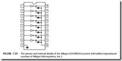
One popular driver IC is the ULN2803 series (from various manufacturers). For example, the ULN2803A device contains eight drivers, each capable of switching up to 50v (DC) at 0.5A. Note that each of the drivers is made up of a pair of Darlington- connected (NPN) BJTs: a Darlington arrangement involves a cascading of two transistors to increase the current gain (see Figure 7.25).

Note that this device includes diodes to protect against ‘inductive kick’ on the chip (see ‘Reliability and safety issues’), which can help reduce component counts.

Note also that:

● The ULN2803A requires no explicit power supply connection.

● Pin 9 should be connected to ground.

● If switching inductive loads, the common cathode of the eight built-in diodes (Pin 10) should be connected to the positive rail of the (high-power) supply (up to +50V).

● The switching speed of this device is around 1 µs.

Driving DC Loads-0144

General-purpose current sources

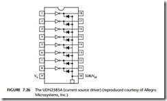
The ULN2803 family are current ‘sinks’: sometimes, however, we require current sources. Here the UDN2585A is an example of a useful source driver. It can source a current of up to 120 mA on each of the eight output lines, at the same time, at volt- ages up to 25V (see Figure 7.26).

Driving DC Loads-0145

The UDN2585A will be used in various examples in this book as a driver for multi- plexed LED displays: see Chapter 21 for further details.

Note also that:

● Pin 9 on the UDN2585A should be connected to the positive rail of the (high- power) supply (up to +25V).

● If switching inductive loads, then the common anode of the eight built-in diodes (Pin 10) should be connected to ground (it does no harm to do this anyway).

● The switching speed of this device is around 5 µs.

Pull-up resistors

When using this pattern, you may need to incorporate pull-up resistors in your hard- ware design, at the buffer inputs. See NAKED LED [page 110] for further details.

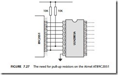
For example, there are no pull-up resistors on pins P1.0, P1.1 on the small Atmel devices, such as the 89C2051. To use these devices, you need to add external pull-up resistors. 10K is a suitable value. Figure 7.27 shows the use of the ULN2803A with an AT89C2051 device.

Note that you will not generally require pull-ups at the buffer outputs.

Driving DC Loads-0146

Hardware resource implications

Every implementation of this pattern uses at least one port pin.

Reliability and safety implications

There are a number of crucial reliability and safety issues associated with the use of high-power DC loads: these are discussed in the pattern BJT DRIVER [page 124]. Please refer to this pattern for further information.

Note that when switching high-power loads in safety-critical applications you may wish to use an IC BUFFER [page 118] between microcontroller port and the IC driver chip.

Portability

These techniques work with all 8051s (and most other microcontroller and micro- processor families).

As usual, if working with port pins that do not have internal pull-up resistors, you need to include such resistors (10K will do) in your design.

Overall strengths and weaknesses

Can be a cheap and easy to use solution if you require more than two medium-power DC outputs.

Unlike transistor drivers, ICs tend to have restricted operating voltages: in many cases, the operating range of such devices is rather less than that of the small 8051s used in many battery-powered applications. This can mean that, if using IC drivers in a battery-powered device, you will be forced to use a more sophisticated (regulated) battery supply: this can add significantly to the application cost. If your application is battery powered, you may find that it is only cost-effective to use an IC driver if four or more output pins require drivers.

Most of the cheap driver ICs require 5V supplies and cannot therefore be easily used in 3V designs.

Related patterns and alternative solutions

The other patterns in this chapter provide alternative solutions.

Example: Displaying error codes

A basic requirement in many embedded applications is an ability to inform the user of errors that may have occurred in the application. These may include, for example, errors in sensors, errors in actuators or errors in slave nodes.

A simple, low-cost way of reporting such errors is to make use of an ‘error port’: if the system is operating normally, this port will be used to display a ‘normal’ code: otherwise, an error code will be displayed.

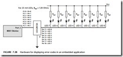
The hardware required to display such codes consists of eight LEDs, each connected to a port pin. To ensure the code is visible under all lighting conditions, high-intensity LEDs may be required. Typical high-intensity LEDs have a current requirement of 25 mA: the total requirement for eight LEDs (200 mA) is therefore far in excess of the current that can be supported by the ‘naked’ microcontroller and is around three times the level that can be supported by an IC buffer.

Figure 7.28 shows a possible hardware solution for displaying the codes, using a ULN2803A as an IC DRIVER .

Driving DC Loads-0147

Note that suitable software for the display of error codes is discussed in Chapter 14.


SSR DRIVER (DC)

SSR DRIVER (DC)
Context

● You are developing an embedded application using one or more members of the 8051 family of microcontrollers.

● You are designing an appropriate hardware foundation for your application.

Problem

How do you ‘switch on’ or ‘switch off’ a piece of high-voltage (DC) electrical equip- ment using a microcontroller?

Background

A solid-state relay is a semiconductor device that was designed to take the place of a conventional electromagnetic (EM) relay. We do not recommend the use of EM relays for switching DC loads and therefore do not consider EM relays until we discuss the switching of AC loads in Chapter 8. If you are unfamiliar with EM relays, you may find it useful to refer to Chapter 8 (and specifically to EMR DRIVER [page 149]) for background information on EM relays before considering this pattern.

Solution

Unlike EM relays, solid-state relays (SSRs) are purely electronic in nature: they have no moving (mechanical) switch contacts. Both DC and AC solid-state relays are avail- able: note that, unlike EM relays, a DC relay will not switch AC supplies and a DC relay will not switch AC supplies: we explain why this is the case later in the pattern.

SSRs provide very high levels of isolation between the ‘control’ and ‘switching’ cir- cuits by optical techniques. The ‘control’ inputs will be connected to one (or more) LEDs. These will then, without any electrical link, control a phototransistor or photo- diode array, which will, in turn, connect to further switching circuitry. In the case of a DC SSR, the switching circuit will typically be based on a MOSFET, and the current- and voltage-switching capabilities will generally be similar to MOSFETs.

Use of SSRs is generally straightforward: the inputs are directly compatible with microcontroller port voltages, and – because of the built-in opto-isolation – there is generally no need to add additional gates between the microcontroller and the SSR.

The examples below will illustrate the use of these devices.

Pull-up resistors

When using this pattern, you may need to incorporate pull-up resistors in your hard- ware design, at the input to the SSR. See NAKED LED [page 110] for further details.

Hardware resource implications

Every implementation of this pattern uses at least one port pin.

Reliability and safety issues

There are a number of general reliability and safety issues associated with the use of high-power DC loads: these are discussed in the pattern BJT DRIVER [page 124]. Please refer to this pattern for further information.

How robust are SSRs?

SSRs are less electrically robust than EM relays: in the presence of excessive voltages (due to back EMF from inductive loads, for example) or where the SSR is subjected to larger currents (possibly due to ‘inrush’), the device will fail. If in doubt, over rate the device: that is, use a 300 V device where a 200 V device would probably do.

One other issue: we have seen people try to use more than one SSR in parallel in order to increase the current rating. This will only rarely work and is never reliable. The problem is that you have no way of ensuring that both relays switch on at exactly the same time. When one relay has turned on, the supply voltage drop will usually mean that the second (and subsequent) SSRs do not turn on – until the first relay fails. Thus, the likely result is that, within around a millisecond, all the relays will blow, in rapid succession.

What’s in a name?

Despite the name, there are important differences between ‘solid-state’ and ‘electro- mechanical’ relays, particularly when it comes to circuit testing. If you are using an EM relay, you can check to make sure that the contacts are closing by using a multimeter to measure the resistance of the switch contacts: this resistance will be essentially zero when the contacts are closed and essentially infinite when they are open. This behav- iour will be observed without connecting up the high-voltage side of the application.

You cannot test an SSR-based circuit in the same manner: most SSRs will always show an infinite resistance when measured with a multimeter. To test an SSR, you need to operate close to the specified operating voltage. Initial tests are therefore best performed (carefully) using a high-voltage load (we usually use an ordinary household lightbulb).

What happens when it goes wrong?

The typical failure mode of an SSR is an output short circuit: this can be dangerous.

Portability

SSRs can be used with any processor type. However, there are other portability issues to consider.

The most important (already briefly mentioned) is that an AC SSR cannot be used to switch DC. The reason for this is that the AC SSR contains zero-crossing detection circuits (see Chapter 8 for details). Because the DC supply never crosses zero, the SSR will never switch on.

Similarly, most DC SSRs are based on MOSFETs. Using a MOSFET to switch AC is ineffective: at best, the device will act as a form of rectifier for a short period, until it overheats.

Overall strengths and weaknesses SSRs do not wear out (in normal use). SSRs are resistant to shock and vibration. SSRs have a high switching speed.

SSRs have high levels of isolation between the ‘control’ and ‘switching’ circuits. SSRs generate only very low levels of electrical noise and generate no

acoustic noise.

SSRs do not exhibit switch bounce.

SSRs can be instantly and irrevocably damaged by excessive voltage and / or current.

The typical failure mode of an SSR is an output short circuit: this can be dangerous.

The ‘switched’ side has a minimum operating voltage and current: these may be quite high, complicating initial testing.

EM relays can usually switch higher voltages and currents.

Unlike an EM relay, the ‘switched’ side exhibits some leakage current in the off-state.

The ‘on’ resistance is typically much larger than that of an EM relays: this trans- lates directly into wasted heat and, hence, the need for heatsinks.

Related patterns and alternative solutions

See the other patterns in this chapter and Chapter 8, for alternative approaches.

Example: SSRs in telecommunication applications

Small DC semiconductor relays are commonly used in telecommunications equip- ment, such as modems, in place of larger EM relays. Indeed, the telecoms market is so important that special-purpose SSRs, intended to be used for telephone current line sensing, are also available (see, for example, products from Erg components).

In modems and similar devices, these SSRs provide 200-300V (DC) output ratings at around 200 mA. They provide a low on resistance (typically 10Ω) and an ‘off’ resist- ance of some 500 MΩ, at voltages up to 4 kV.

Example: Open-loop DC motor control

In MOSFET DRIVER [page 139] we presented an example of a MOSFET used for open- loop DC motor control (see Figure 7.34 for details).

If we use an appropriate SSR we can simplify this circuit considerably. For example, our motor required 2A (continuous) at up to 12V for correct operation. Here we can use an IOR PVNO12 SSR. Unlike the majority of SSRs, this can switch AC or DC loads, of up to 20 V, 4.5A. It has no zero-crossing detection. The control current is a maxi- mum of 10mA, which is compatible with our microcontroller. Figure 7.35 shows the required circuit.

Note that an important advantage of the SSR solution is that it provides a greater degree of isolation between the controller and the motor itself. Note also that, to con- trol the speed of this motor, pulse-width modulation may be possible: see HARDW ARE PWM [page 808] and SOFTW ARE PWM [page 831].

Driving DC Loads-0153


Driving AC loads

Introduction

Consider some problems:

● A pump in a domestic or industrial heating system must be switched on and off at preset times.

● A series of high-intensity lights around the perimeter of a factory complex are to be activated in the event of a security incident.

● An electrical heater in a brewery must be used to maintain a precise temperature.

● The motor in a washing machine must go through a pre-programmed series of movements.

In these – and many other applications – we need safely and reliably to control comparatively high-level AC supplies. In this chapter we will consider two popular approaches to this problem

EMR DRIVER [page 149]

SSR DRIVER ( AC ) [page 156]


BJT DRIVER

BJT DRIVER

Context

● You are developing an embedded application using one or more members of the 8051 family of microcontrollers.

● You are designing an appropriate hardware foundation for your application.

Problem

How do you drive DC loads requiring currents of up to around 2A, from the port of an 8051 microcontroller?

Background

A bipolar-junction transistor (BJT) is a three-terminal semiconductor device, devel- oped in the early 1950s. The full name (or acronym) will be used here to distinguish this pattern from the FET (field-effect transistor) considered later in this chapter.

As far as we are concerned, a BJT is most useful as a current-controlled switch. We will not be concerned here with details of their underlying operation but will, instead, focus on the ways in which these transistors may be used to allow a micro- controller to drive a medium-power DC load.

Solution

BJT transistors come in two basic forms: PNP and NPN (Figure 7.15).

Driving DC Loads-0132

[Note: For our purposes, the main value of the BJT is that it acts as a voltage controlled switch. In the case the PNP device, current flow- ing from the base is used to control a much larger current through the load. In the case of the NPN device, current flowing into the base of the device performs the same function.]

To ‘turn on’ the transistor, we need to supply (in the case of NPN) or sink (in the case of PNP) a base current given by the formula:

Driving DC Loads-0133

where hfe is the transistor ‘gain’. This varies from values of around 15 to around 800: values of 100 are typical for the types of devices we are considering. As previously noted, the pins of an 8051 device can sink or source around 20 mA of current (at most): thus, using a suitable BJT, we can control currents of up to around 2A (20 mA multipled by hfe).

We will give two specific examples here: a PNP transistor switch and an NPN transistor switch.

A PNP transistor switch

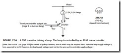
To illustrate the type of BJT application we will be concerned with in this pattern, consider Figure 7.16. This shows a small lamp (5V, 500 mA), connected to a PNP tran- sistor. Note that, in this circuit, almost any PNP transistor will work, provided it has an hfe value of around 100 (given on the data sheet), and can handle a collector cur- rent of around 500 mA. Note that in this case, a Zetex ZTX 751 transistor is used. This can control a (collector) current of up to 2A, which is a suitable level for a wide range of applications. Such devices are not expensive: expect to pay around $0.30 per tran- sistor (multiples of 1,000 devices).

Briefly, the circuit operates as follows. When the microcontroller pin is at Logic 0, current will flow out of the base of the transistor, driving the device into saturation: the required load current will then flow and the lamp will light. When the microcon- troller pin is at Logic 1, however, no current will flow from the base of the transistor and the load current will be (essentially) 0.

Overall, the significant thing about this circuit is that a very small control current flow- ing out of the base of the transistor (Ibase in the figure) controls the flow of a much larger current (Iload) flowing through the lamp. This is the basis of all BJT interface circuits.

Pull-up resistors

When using this pattern, you may need to incorporate pull-up resistors in your hard- ware design. (See NAKED LED [page 110].)

Buffering the output

We use BJTs to allow us to control comparatively high-power loads. The loads can change: for example, devices can short-circuit, motors can stall or the whole device may suffer physical damage. In such circumstances, the microcontroller port can be subject to high voltages and / or currents. This may result in the whole microcon- troller being rendered inoperative.
Driving DC Loads-0134

[Note: See NAKED LED [page 110] for details of pull-up resistors, one of which may be required here. Note the lamp supply voltage is, here, assumed to be 5V: however, the load supply voltage need not be the same as the controller supply voltage.]

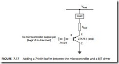
In many circumstances, it is safer to use a buffer to protect the microcontroller in the event of a problem with the load or BJT driver. Figure 7.17 shows a suitable circuit.

Note that we have used two inverter gates to obtain the required logic. As multiple gates are available on a single 74×04, and this is a low-cost buffer, this can be a good solution. Alternatively, the 74×241-based circuit in Figure 7.18 may be used.

Note that, for reasons discussed in IC BUFFER [page 118], a pull-up resistor may be required at the base of the transistor in both of these buffer circuits, if you use TTL technology.
Driving DC Loads-0135

Driving DC Loads-0136

In Figure 7.19 we have used an inverter to both invert the port output (so that a Logic 0 output is now required to drive the load) and to provide a degree of isolation between the transistor and the microcontroller.

Note that in Figure 7.19, we need to ‘source’ current: that is, the direction of conven- tional current flow is into the base of the transistor. As we discussed in NAKED LOAD [page 115], the need to source current may be problematic in some circumstances. For this reason, drivers based on PNP transistors can be slightly more portable.

Hardware resource implications

Every implementation of this pattern uses at least one port pin.

Reliability and safety implications

Pin reset values

After the system is reset, the contents of the various port special function registers (SFRs) are set to 0xFF. This fact has very important safety and reliability implications.

Consider, for example, that you have connected a motorized device to a port and that the device is activated by a ‘Logic 1’ output: that is, a ‘1’ output on a port pin. When the microcontroller is reset, the motorized device may be activated and begin moving. Even if you set the port outputs to 0 at the start of your program, the motor may be ‘pulsed’ briefly, before you are able to stop it. This can, in some systems, lead to the injury or even death of users of the system or those in the immediate vicinity of the system.

Because the output pins are ‘reset high’ it is important to ensure that any devices which have safety implications are connected to the microcontroller in such a way that they are ‘active low’: that is, that an output of ‘0’ on the relevant port pin will activate the device.

Switching on lamps and DC motors

We have presented various equations in this chapter that allow the value of series resis- tors to be calculated for use in drive circuits like that shown in Figure 7.19. In presenting such equations we have implicitly assumed that the load resistance itself is fixed.

In fact, not all devices present a fixed resistive load. For example, when controlling lamps or DC motors, the initial current required may be very high. This surge of cur- rent may last several hundreds of milliseconds, before it settles to the steady-state value. Your drive circuit needs to be capable of surviving the initial current surge.

One way of dealing with inrush currents is to ‘over rate’ your drive circuit. This means that if, for example, your load is a lamp or motor with a steady-state current requirement of (say) 1A, you should rate your drive circuit at (say) 10A or more, so that you can deal with the inrush current. Please note that it is seldom possible to guess the likely inrush currents. Check the data sheets – they will provide this infor- mation. In the absence of accurate data, assume a factor of at least 10.

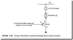
Another way of solving this problem is to use what is known as a thermistor in series with the load (Figure 7.20). These have a resistance of around 1–2 Ω when cold: when they warm up (which they do when carrying current) the resistance drops around 0 Ω. Even a small amount of initial resistance will greatly reduce the impact of the inrush current.

Please also note that it is easy to overlook or ignore this issue. Not all drive cir- cuits will fail immediately if subjected to excessive loads and your test circuit may operate reliably on the bench. However, stressing any drive circuit beyond its maxi- mum ratings will dramatically shorten its useful life and it will fail in the field. If in any doubt: over rate by at least a factor of 10 and add a thermistor.
Driving DC Loads-0137

Switching off inductive DC loads

Just because you have managed to switch on a load safely does not, unfortunately, mean that you problems are solved, if your load is inductive.

An inductive load is anything containing a coil of wire: common examples are electromechanical relays and motors. Switching off such loads must be carried out with great caution because, when the current is removed, the voltage across the inductor will increase rapidly. The rapid increase in voltage occurs because the opera- tion of the inductor is defined by the equation:

Driving DC Loads-0138

Here, V is the voltage across the inductor, L is the inductance, and dI/dt is the rate of change of current flow. If we suddenly remove the current (that is, ‘switch off’ the inductor), the resulting rapid change in current will be translated into a rapid voltage increase. This ‘inductive kick’ can be enough to destroy logic gates or any other form of drive circuitry linked to the load. To protect these circuits, a diode can be used to block the ‘kick’ (Figure 7.21).

Please note that the diode used must be able to handle not only the steady-state current but also the turn-off current. The ubiquitous and cheap 1N4004 diode can handle 1A, and is appropriate for many circuits. Where this is not sufficient, a wide range of other capacities are available: for example, the 1N5401 (3A, 100V), the 40HF10 (40A, 100V) or the 70UR60 (250A, 600V). Note that the prices increase dra- matically with current capacity: the low-power diodes cost a few cents, while the high-power alternatives may cost $10.00.

Driving DC Loads-0139

Please note (again) that it is easy to overlook or ignore this issue. Not all drive circuits will fail immediately if subjected to excessive loads and your test circuit may operate reliably on the bench. However, stressing any drive circuit beyond its maxi- mum ratings will dramatically shorten its useful life and it will fail in the field. If in any doubt, use a suitable diode or resistor.

Protecting again load faults

The use of thermistors, diodes and inrush resistors is designed to protect the switch- ing circuit under normal conditions. When working with high-power loads, you also need to deal with the problems caused by damage to the load. In particular, we need to consider the possibility that the load will be short-circuited.

A particular problem arises with semiconductor switching devices such as BJTs. The thermal mass of such semiconductor devices is very low: this means that an excessive current flow – caused, for example, by a short or a stalled motor – will very rapidly take the device out of the safe operating region (see Lander, 1993; or Rashid, 1993, for details). To protect against this, it is essential that you use a fuse in series with the load.

Note that an ‘ordinary’ fuse will not be adequate: the fuse must blow very rapidly to avoid damage to the semiconductor device: such devices are usually labelled ‘high speed’ and will be described as being suitable for semiconductor protection.

Portability

These techniques work with all 8051s (and most other microcontroller and micro- processor families).

As usual, if working with port pins that do not have internal pull-up resistors, you need to include such resistors (10K will do) in your design.

Overall strengths and weaknesses

Software developers sometimes seem to hold the view that discrete transis- tors are ‘old fashioned’ and have now been replaced by IC equivalents. This is not the case. In many applications, particularly where a small number of relatively low- and medium-power drivers are required, discrete transistors are widely used, not least because they are available for under $0.10 each (around half the price of ICs), even in small quantities: as such they can rep- resent a very cost-effective solution.

BJTs can operate at very low voltages, compatible with low-voltage micro- controllers.

The maximum BJT gain of around 100 means that, in most circumstances, we are restricted to current flows of around 1A–2A, if we use a single transistor. Single MOSFETs, by comparison, can readily switch loads of 100A.

The switching speed of transistors (and in particular the switch-off speed) can be around 0.5 µs. This may sound fast, but, particularly in some pulse-width modu- lation applications (see HARDW ARE PWM [page 742]), may not be fast enough.

Related patterns and alternative solutions

The main alternatives to the BJT DRIVER are IC DRIVER [page 134] and MOSFET DRIVER

Example: Driving a high-power IR LED transmitter

Infra-red (IR) LEDs are widely used in domestic applications for remote control. They are also a component in many security systems. IR LEDs often have higher current requirements than conventional LEDs, but are otherwise connected in the same way.

For example, the Siemens SFH485 IR LED requires a current of 100 mA, at a for- ward voltage of 1.5V. If we wish to drive this LED using (say) Port 1 of an 8051 microcontroller, then a variation on the circuit from Figure 7.16 can be used.

Here, we will use a low-cost (PNP) transistor: a 2N2905. This can handle a maxi- mum load current of 600 mA. With ILED at 100 mA, a supply voltage of 5V and an

LED forward voltage of 1.5V, the required value of R2 is:


The saturation voltage (VCE) for the transistor of 0.4V is taken from the transistor data sheet.

Here we would use the next standard resistor value, in this case 33Ω. Note that the nearest value is 30Ω: however, by using this we run the slight risk of running the LED at too high a forward voltage, and reducing the life of this component.


Driving DC Loads-0140