IC DRIVER
Context
● You are developing an embedded application using one or more members of the 8051 family of microcontrollers.
● You are designing an appropriate hardware foundation for your application.
Problem
How do you safely control multiple, medium-power DC loads from a single micro- controller port?
Background
See IC BUFFER [page 118] for general background material.
Solution
We consider examples of both ‘sink’ and ‘source’ driver ICs in this section.
General-purpose current sinks
Most general-purpose IC ‘sink’ drivers are suitable for switching DC voltages of up to around 50 V (higher voltage variants are available). They are typically capable of sink- ing currents of around 0.5A to 2A.
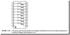
One popular driver IC is the ULN2803 series (from various manufacturers). For example, the ULN2803A device contains eight drivers, each capable of switching up to 50v (DC) at 0.5A. Note that each of the drivers is made up of a pair of Darlington- connected (NPN) BJTs: a Darlington arrangement involves a cascading of two transistors to increase the current gain (see Figure 7.25).
Note that this device includes diodes to protect against ‘inductive kick’ on the chip (see ‘Reliability and safety issues’), which can help reduce component counts.
Note also that:
● The ULN2803A requires no explicit power supply connection.
● Pin 9 should be connected to ground.
● If switching inductive loads, the common cathode of the eight built-in diodes (Pin 10) should be connected to the positive rail of the (high-power) supply (up to +50V).
● The switching speed of this device is around 1 µs.
General-purpose current sources
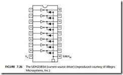
The ULN2803 family are current ‘sinks’: sometimes, however, we require current sources. Here the UDN2585A is an example of a useful source driver. It can source a current of up to 120 mA on each of the eight output lines, at the same time, at volt- ages up to 25V (see Figure 7.26).
The UDN2585A will be used in various examples in this book as a driver for multi- plexed LED displays: see Chapter 21 for further details.
Note also that:
● Pin 9 on the UDN2585A should be connected to the positive rail of the (high- power) supply (up to +25V).
● If switching inductive loads, then the common anode of the eight built-in diodes (Pin 10) should be connected to ground (it does no harm to do this anyway).
● The switching speed of this device is around 5 µs.
Pull-up resistors
When using this pattern, you may need to incorporate pull-up resistors in your hard- ware design, at the buffer inputs. See NAKED LED [page 110] for further details.
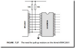
For example, there are no pull-up resistors on pins P1.0, P1.1 on the small Atmel devices, such as the 89C2051. To use these devices, you need to add external pull-up resistors. 10K is a suitable value. Figure 7.27 shows the use of the ULN2803A with an AT89C2051 device.
Note that you will not generally require pull-ups at the buffer outputs.
Hardware resource implications
Every implementation of this pattern uses at least one port pin.
Reliability and safety implications
There are a number of crucial reliability and safety issues associated with the use of high-power DC loads: these are discussed in the pattern BJT DRIVER [page 124]. Please refer to this pattern for further information.
Note that when switching high-power loads in safety-critical applications you may wish to use an IC BUFFER [page 118] between microcontroller port and the IC driver chip.
Portability
These techniques work with all 8051s (and most other microcontroller and micro- processor families).
As usual, if working with port pins that do not have internal pull-up resistors, you need to include such resistors (10K will do) in your design.
Overall strengths and weaknesses
Can be a cheap and easy to use solution if you require more than two medium-power DC outputs.
Unlike transistor drivers, ICs tend to have restricted operating voltages: in many cases, the operating range of such devices is rather less than that of the small 8051s used in many battery-powered applications. This can mean that, if using IC drivers in a battery-powered device, you will be forced to use a more sophisticated (regulated) battery supply: this can add significantly to the application cost. If your application is battery powered, you may find that it is only cost-effective to use an IC driver if four or more output pins require drivers.
Most of the cheap driver ICs require 5V supplies and cannot therefore be easily used in 3V designs.
Related patterns and alternative solutions
The other patterns in this chapter provide alternative solutions.
Example: Displaying error codes
A basic requirement in many embedded applications is an ability to inform the user of errors that may have occurred in the application. These may include, for example, errors in sensors, errors in actuators or errors in slave nodes.
A simple, low-cost way of reporting such errors is to make use of an ‘error port’: if the system is operating normally, this port will be used to display a ‘normal’ code: otherwise, an error code will be displayed.
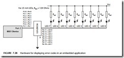
The hardware required to display such codes consists of eight LEDs, each connected to a port pin. To ensure the code is visible under all lighting conditions, high-intensity LEDs may be required. Typical high-intensity LEDs have a current requirement of 25 mA: the total requirement for eight LEDs (200 mA) is therefore far in excess of the current that can be supported by the ‘naked’ microcontroller and is around three times the level that can be supported by an IC buffer.
Figure 7.28 shows a possible hardware solution for displaying the codes, using a ULN2803A as an IC DRIVER .
Note that suitable software for the display of error codes is discussed in Chapter 14.


