GETTING STARTED:The Hardware and Software

The Hardware and Software

This chapter lets you know what you need in the way of minimum hardware and soft- ware to get started and what you need to do to set it up and get it ready for use.

List of hardware and what comes with it

N The LAB-X1 board (with software CD ROM)

N Power supply for LAB-X1 (with wall-mounted transformer)

N Serial port, parallel port, or USB port programmer for the board (with software CD ROM connection cable for LAB-X1 board [10-pin], cable to go from computer to programmer)

N Power supply for the programmer (with wall-mounted transformer)

N PIC 16F877A microcontroller or equivalent (see list in Chapter 1) List of the required software

N PICBASIC PRO compiler

N MicroCode Studio editor software for writing the programs List of the required information

N Data sheet for PIC 16F877A microcontroller downloaded from the Internet or the CD

List of computer equipment you already should have

N 1Wintel computer (IBM-PC or compatible with hard drive), CD reader (needed only to read software on CD ROMs but nothing else), printer, Windows operating system, and access to the Internet. (A broadband connection is strongly recommended.)


INTRODUCTION TO MICROENGINEERING LABS’ LAB-X1 EXPERIMENTAL BOARD:THE MICROCONTROLLER

INTRODUCTION TO MICROENGINEERING LABS’ LAB-X1 EXPERIMENTAL BOARD

THE MICROCONTROLLER

The PIC 16F877A microcontroller (which is a necessary component on the board) is not provided because each of the compatible PIC microprocessors available has varying features, and you need to select a unit that suits the application that you have in mind. We will be using the recommended PIC 16F877A and 18F4331 microcontrol- lers for all our experiments. If you want to use a different processor, be sure to check for pin-to-pin compatibility on the web. Data sheets can be downloaded for all the

RUNNING SMALL MOTORS-0000

microcontrollers at no charge from the Internet. The commonly used 40-pin for pin- compatible MCUs are the 16F873, 16F874, 16F876, 16F877, 18F4331, and 18F4431.

They share similar power and pinout layouts but exhibit different capabilities. Other PICs may also be used.

The following 40-pin PICs will work in the LAB-X1

RUNNING SMALL MOTORS-0001


More Control Systems:Production Systems

Production Systems

There are two main types of production system. Manufacturing systems include materials and component handling technologies such as conveyors and robots, which work with machine

PIC Microcontrollers-1349

tools and assembly subsystems to produce discrete product items, such as motor vehicles. Process control systems are those that supervise continuous flow production, such as an oil refinery, where the product is a liquid, gas, powder, granules or similar material. This typically involves sequence control of pumps and valves, controlling storage tanks and pipework installations, with inputs from flow, level, temperature sensors, etc., to form a closed loop system. All these systems will contain microprocessor-based controllers, both within the PLCs that control the component subsystems, and within the dedicated controllers built into machines, tools and robots.

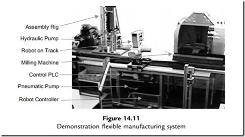
A flexible manufacturing system (FMS) workcell has machines that can be reprogrammed to produce a variety of similar products. Typically, it consists of pick-and-place robots working alongside machine tools to manufacture components and assemble them into a finished product. A basic demonstration system is shown in Figure 14.11. It consists of a milling machine, a hydraulic assembly rig and a component handling robot. It is designed to machine and assemble a simple product consisting of three components: a printed circuit board (PCB) in a milled plastic enclosure with a press-fit cover. The robot places a plastic blank in the mill, which machines the casing; the robot then retrieves the enclosure, places it in the assembly rig and inserts the PCB, and the cover is fitted by the hydraulic press.

A block diagram (Figure 14.12) shows how the subsystems of the workcell interconnect. The digital signals in the system operate at 24 V, the higher voltage providing better noise immunity than TTL (5 V) levels. The various controllers signal to each other with, usually, individual active low signals, to control the sequence of operations. For example, when the mill has finished, it asserts (sets active) a ‘Mill Ready’ signal to the robot controller, which triggers the robot program to pick up the finished workpiece. The robot slide, the press rig and the mill are all controlled by their own PLCs, with the main PLC in charge of the overall system. The robot

PIC Microcontrollers-1350

controller needs a reasonably powerful processor system, because of the complex calculations required for the robot movement. This and the PLCs are programmed from a PC, via a serial port. The main system PLC remains connected to the PC, which then operates as a supervisory control and data acquisition (SCADA) system host when the system is running. It provides a virtual control panel and graphical status display of the system as it runs, reading status bits and writing control bits in the main PLC, and modifying the display accordingly.

Both manufacturing and process control systems can be managed by a SCADA network to provide integrated, centralized control and performance monitoring. A typical display is shown in Figure 14.13. Powerful software suites support the communication and presentation of the information, principally using on-screen interactive mimic diagrams and dynamic database management to give a complete overview of the system operation.

In the industrial environment, the subsystems need to be mounted and connected together using physically robust methods. A typical control cabinet is shown in Figure 14.14. The vulnerable parts of the control system, such as PLCs, microcontroller boards, terminal blocks, power supplies, communication modules and keypads, are protected in a steel cabinet. Another important feature is the emergency stop buttons.

PIC Microcontrollers-1351

PIC Microcontrollers-1352


More Control Systems:PLC Control

PLC Control

Programmable logic controllers are often used for sequential control in industrial systems. The PLC is a self-contained sequence controller, built around a microprocessor or microcontroller,

PIC Microcontrollers-1343

but with all the interfacing built in. PLCs also use more user-friendly programming techniques, such as ladder logic. A small Mitsubishi PLC is shown in Figure 14.7.

The PLC can be programmed to act like a set of relays to give a particular output sequence in response to switched inputs, which can be manual inputs or derived from sensors. It is suitable for controlling systems where motors, heaters, valves and other loads must be switched directly from a power supply. The same machine tool seen in the previous example is now shown under PLC control in Figure 14.8.

The PLC has inputs labeled X0, X1, X2 and X3. These are detected as ‘on’ when connected to 24 V via an external switched sensor or control input. The PLC is programmed to operate the outputs, labeled Y0 and Y1, according to the input sequence. The outputs are also simple switched contacts, as in the normally open contact of a relay, which operate a load circuit with an external supply. They are typically designed to handle high power loads operating with mains voltage, or three-phase supplies. If necessary, the PLC outputs can control external

PIC Microcontrollers-1344

contactors (load relays) if the load current exceeds the PLC output contact rating. The control and load circuits are electrically isolated from each other, for safety, reliability and ease of use. The PLC inputs use opto-isolators, where the on/off signal is passed as infrared light, giving complete electrical isolation between the input and controller internal circuits.

PIC Microcontrollers-1345

PIC Microcontrollers-1346

The program for the PLC can be created in ‘ladder logic’ form (Figure 14.9), which allows the control program to be defined as if the PLC contained the relay system shown in Figure 14.6. The graphical program corresponds to the wiring diagram of the low-voltage (control) side of the relay system. Ladder logic uses a basic set of three symbols: normally open contacts, inverted contacts and output coils. These are associated by label with a physical input (Xn) or output (Yn). The normally open contacts represent external normally open contacts connected to the corresponding input; when the real contact closes, the contact in the program is closed. An inverted contact (X1) simply reverses the polarity of the external switch. The sides of the ladder correspond to the 24 V supply rails in the real circuit, so an output goes on when there is a closed path through the contacts in that rung of the ladder to switch on the coil, which operates the associated output in the PLC. The graphical program is entered on a host PC and converted to a machine code program, which is downloaded to the microcontroller in the PLC, in the same way as an assembler program.

In the ladder diagram, the system will come on when the ‘Start’ input is pressed, if the ‘Stop’ button is open and the ‘Guard’ switch is closed (guard closed). The ‘Stop’ button itself is normally open, but is inverted in the ladder program so it operates as if normally closed. The contact labeled Y1 (pump) closes because the virtual circuit is complete. The associated contact Y1 therefore also closes, which ‘holds on’ the output, even when the start button is released. A second Y1 contact then switches on the motor, as long as the overload cut-out is closed (no overload). The machine is then running. If the motor is overloaded, the thermal cut-out operates and switches off the motor, but the pump stays on to maintain

coolant feed. If the guard is opened or the stop button pressed, then both motor and pump go off. Output Y1 corresponds to relay 1 coil in the relay-controlled system, and Y0 to relay 2 coil.

Ladder programming was designed as a user-friendly method for creating this type of sequential control program, for engineers used to dealing with hard-wired relay systems. It was the first graphical programming method, of which there are now many, such as Flowcode for the PIC.


INTRODUCTION TO MICROENGINEERING LABS’ LAB-X1 EXPERIMENTAL BOARD:SOFTWARE COMPILER

SOFTWARE COMPILER

The PICBASIC PRO BASIC software compiler provided by micro Engineering Labs provides the functions needed to control all aspects of the hardware provided by Microchip Technologies as a part of their large PIC offering. All the functions avail- able on the PIC 16F877A microcontroller that we will be using are accessible from the software. The PICBASIC software will write software for almost the entire family of PIC microcontrollers. You will be able to use this compiler for all your future projects; it is a very worthwhile investment.

ADDITIONAL HARDWARE

The following hardware can be added to the LAB-X1 without making any modifica- tions to the board. These hardware items fit into sockets or onto pins that are provided on the LAB-X1 as shipped. Not all devices can be mounted simultaneously because some addresses are shared by the sockets provided. In our experiments, we will popu- late only one of the empty sockets at a time, to make sure that there are no conflicts. (There is no need to use more than one device at one time for any one experiment so this will not be a problem.)

Memory chips:

N I2C memory chip

N SPI memory chip Microwire memory chips:

N 12 bit A to D converter chip

N NJU6355

Real time clock chips:

N DS1202 N DS1302 N LTC1298

Thermometer chip:

N DS1802

Serial interface chip:

N RS485

RC servos:

N Two hobby R/C servos can be controlled simultaneously; not provided.

The LAB-X1 provides two sets of pins for the R/C servos. All standard model air- craft servos can be used and you can use either one or two of them. (Using these is essentially an exercise in creating pulse width modulated signals and profiles that are used in the R/C industry.)

40-PIN DEVICES

All 40-pin MCUs provided by Microchip can be accommodated in the 40-pin ZIF socket provided on the board. Check for compatibility with the pin layout before selecting and buying your MCU. The recommended PIC 16F877A that we are using is an excellent choice for learning if you have no specific use in mind.

We will also be using the 18F4331 for the experiments needing encoder interfacing with the microprocessor. This chip has the ability to keep track of the encoder position automatically, which is a very useful property for our purposes.


INTRODUCTION TO MICROENGINEERING LABS’ LAB-X1 EXPERIMENTAL BOARD:BREADBOARDING AND EXPANSION

BREADBOARDING AND EXPANSION

All 40 pins of the MCU have been provided with extra predrilled PC board holes. These can be used to extend the signals from these pins to an off board location for experimentation. The extensions are easily made with standard 0.1 inch on center pins and matching cables and headers.

A small breadboard space is provided on the LAB-X1 itself to allow the addition of a limited number of hardware items that you may need to experiment with.

See the Internet support web site www.encodergeek.com for availability of ready- made headers and cables and so on for use with the LAB-X1.

SPECIAL PRECAUTIONS AND NOTES OF INTEREST

The following caveat could have been placed later in the book but is included here to encourage you to select the programmer best suited to your needs.

Pin B7 on the LAB-X1 is connected to a programming pin on the EPIC parallel programmer at all times, and the programmer forces this pin high. If you are using this pin in your experiment and you need to have it be low, you must disconnect the EPIC programmer to release the pin. The major benefit of using the parallel programmer is that it frees up your computer’s serial port for communications with the LAB-X1, but if you are using a USB programmer, it can be left connected to the LAB-X1 at all times. This is the reason I recommend the USB programmer.

Resistor R17, which is connected to the keypad, is of no consequence to the opera- tion of the LAB-X1. It is needed for some PIC programming functions and can be ignored for our purposes.

DATA SHEETS

The hardest part of using these microcontrollers is understanding the huge data sheets—often 400 pages or so. Since each data sheet is similar but different from every other data sheet, you are advised to select one or two microcontrollers to get familiar with and use them for all your initial projects. In this workbook the three that are discussed are the PIC 16F84A (this chip will not fit in the 40-pin socket provided but is a good alternate choice) for your small projects and the PIC 16F877A for larger, more comprehensive projects. Each of these uses flash memory and can therefore be programmed over and over again with your programmer and a programming socket. The processor you select will be determined by the kind of I/O and internal features that you need and the availability of inexpensive OTP (one-time programmable) equivalents if you are going to go into production. We will use the 18F4331 also but only for the encoded motor experiments.

A lot of the information in the data sheets is more complicated and detailed than we need to worry about; we can do a lot of useful work without understanding it in every detail. For example, the timing diagrams and other data about the internal workings of the chips are beyond what we need to understand at the level of this book. Our main interest should be in what the various registers are used for and how to use them prop- erly and effectively, as well as being able to set the various registers in the system so that we can activate the features we need for each particular project. Understanding timers and counters is a part of this. The entire interaction of the microcontroller with its environment is determined by the I/O pins and how they are configured, so know- ing how to configure the I/O competently is very important.

The data sheets are available as PDF (portable document format) files on the Internet from the microEngineering Labs web site or from the Microchip web site. Download these onto your computer for immediate access when you need them. Keeping a window open specifically for this data is very handy, but you will also want to print out some of the information to have it in your hands.

The areas of the data sheet that support our needs are the following:

1. Understanding and becoming familiar with what has already been defined by the compiler software as it relates to the software

2. Getting familiar with the addressing and naming conventions used in the data sheet

3. Understanding the use of the various areas of memory on the MCU

4. Learning how to assign and use the I/O pins to your best advantage

5. Understanding how to use the PBP software to its best advantage and writing pro- grams that are as fast as possible

6. Getting familiar with the register naming conventions and usage.


Hardware Prototyping:DIZI Application Outlines

DIZI Application Outlines

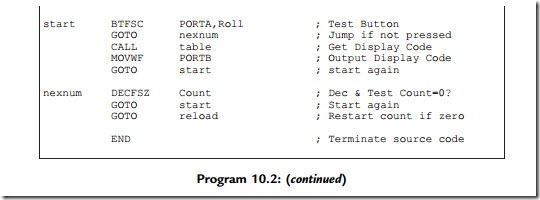
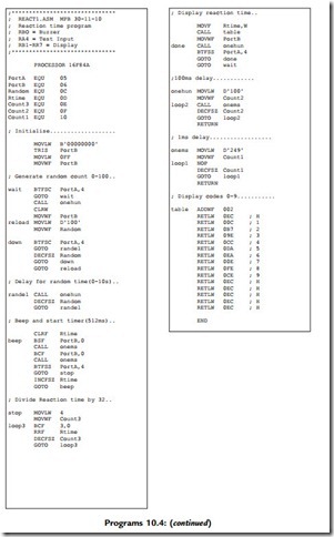
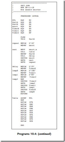
A further eight applications are specified below, and the source code for each is listed in

Programs 10.4. They can be downloaded from www.picmicros.org.uk, and tested in simulation

PIC Microcontrollers-1273

PIC Microcontrollers-1274

mode in MPSIM or ISIS (if available). If the DIZI hardware is constructed, they can be programmed into a 16F84A chip using an out-of-circuit programmer.

HEX1 Hex Converter

The hexadecimal number corresponding to the binary setting of the DIP switch inputs is displayed. The input switches select from a table of 16 seven-segment codes which drive the display in the required pattern for each hex digit: 0, 1, 2, 3, 4, 5, 6, 7, 8, 9, A, b, C, d and E. Note that numbers B and D are displayed in lower case so that they can be distinguished from 8 and 0, respectively.

MESS1 Message Display

A sequence of characters is displayed for about 0.5 s each. Most letters of the alphabet can be obtained on the seven-segment display in either upper or lower case, for instance ‘HELLO’. The number of characters must be set in a counter, or a termination character used.

SEC1 Second Counter

An output is displayed which counts down exactly once per second, from 0 to 9, and then repeats. A table of display codes is required as in the Hex Converter application. A 1 s time delay can be achieved using the hardware timer (Chapter 6) and spare register. A tick could be produced at the audio output by pulsing the speaker at each step.

REACT1 Reaction Timer

The user’s reaction time is tested by generating a random delay of between 1 and 10 s, outputting a beep, and timing the delay before the input button is pressed. A number representing the time between the sound and the input, in multiples of 100 ms, should be displayed as a number 0e9, giving a maximum reaction time of 900 ms.

PIC Microcontrollers-1275

PIC Microcontrollers-1276

An audio frequency generator outputs frequencies in the range 20 Hz to 20 kHz. The sounder output is toggled with a delay between each operation determined by the frequency required, as in the BUZZ1 program. For example, for a frequency of 1 kHz, a delay of 1 ms is required, which is 1000 instruction cycles at a cycle time of 1 ms. The information on program timing must be studied in Chapter 6. The delay time, and hence the frequency, can then be incremented using the input button, and range selection with the input switches might be incorporated, as there are only 255 steps available when using an 8-bit register as the period counter.

MET1 Metronome

An audible pulse is output at a rate set by the DIP switches or input buttons. The output tick can be adjustable from, say, 1 up to 4 beats per second, using the interrupt button to step the speed up and down, and the input button to select up or down. A software loop or the TMR0 register can be used to provide the necessary time delays.

BELL1 Doorbell

A tune is played when the input button is pressed, using a program look-up table for the tone frequency and duration. Each tone must be played for a suitable time, or number of cycles, as required by the tune. The program can be elaborated by selecting a tune using the DIP switches, and displaying the number of the tune selected.

GIT1 Guitar Tuner

The program will allow the user to step through the frequencies for tuning the strings of a guitar, or another musical instrument using the input button, or selecting the tone at the DIP switches. The program could be enhanced by displaying the string number to be tuned. The tone frequencies will be generated as for the doorbell application. The digit display codes would also be required in a table.

PIC Microcontrollers-1277

PIC Microcontrollers-1278PIC Microcontrollers-1279PIC Microcontrollers-1280PIC Microcontrollers-1281PIC Microcontrollers-1282

be scanned in rows and columns. A key press is detected as a connection between a row and column. The pull-up resistors ensure that all lines default to logic ‘1’. If a ‘0’ is applied to one of the column terminals (C1, C2, C3), and a key is pressed, this ‘0’ can be detected at the row terminal (R1, R2, R3, R4). If the keypad terminals are connected to a PIC port, and a ‘0’ output in rotation to the three columns, a key can be detected as a combination of the column selected and the row detected. Column terminals can be set as outputs, and rows as inputs. Draw a flowchart to represent the process for converting each decimal key into the corresponding BCD number.

(b) A lock function may be implemented by matching an input sequence with a stored sequence of, say, four digits, and switching on an output to a door solenoid if

a match is detected. Specify the hardware and outline the program for the lock application.

(c) Design, build and test an electronic lock system using the keypad shown, a suitable PIC and an LED to indicate the state of the lock (ON ¼ unlocked). Research the design for the interface to a solenoid operated door lock.

Note: Keypad scanning is used in Program 13.1, and a lock application outlined in Appendix


More Control Systems:Control System Design

Control System Design

The microcontroller or microprocessor forms the basis of most control systems. A dedicated microprocessor design allows the memory and interfacing to be designed separately, but, because of the range of microcontrollers now available and the additional system design work required, this is now much less likely to be a cost-effective solution. In either case, the peripheral interfacing must also be designed at component level.

By contrast, the PLC offers an off-the-shelf hardware package, requiring no external electronics to interface it. PLCs are generally designed around dedicated microcontrollers, with a built-in proprietary operating system. The program is traditionally written in ladder logic and is compiled automatically to machine code. Additional programming tools are also usually supplied by the individual manufacturer to meet more complex specifications and project management requirements. Overall, the PLC is robust, and easy to install and program, with a variety of communication interfaces to support system integration.

In industrial systems, the PC can function as a general purpose administrative computer, programming host, design workstation, SCADA display, network client or server. As a system controller, the PC is most often connected to client PLCs, robots and machine tools via

a network, with the PLCs controlling the target hardware, as in the FMS above. The PC can also act separately as a programming terminal for the different programmable devices, then SCADA host when the system is operational. It can also act as a computer-aided design or electronic computer-aided design (CAD/ECAD) workstation, component database server or just a plain old word processor!

Table 14.1 provides a comparison of the advantages and disadvantages of the different forms of system control outlined above. A reasonable working knowledge of all the options is required in order to select the most appropriate technology for any given application. The microcontroller is central to all these technologies.

Questions 14

1. Outline the differences between the Intel 8051 microcontroller and an equivalent PIC MCU in terms of their general internal architecture and consequent performance. (4)

2. State two advantages and two disadvantages of the conventional processor system over the microcontroller in designing a system to meet a particular specification. (4)

3. Explain briefly the advantages of using a PLC compared with a microprocessor system in

control applications. (4)

4. Draw a flowchart for Program 14.2 to show the control sequence clearly. (7)

5. List six possible functions of the PC in a production system. (6)

6. Match up the controller type with the most appropriate programming language or technique:

(a) Small microcontroller 1. ‘C’

(b) CISC Microprocessor 2. None

(c) Relay system 3. Mimic

(d) PLC 4. Assembler

(e) SCADA 5. Ladder Logic. (5)

Answers on pages 425e6. (Total 30 marks)

Activities 14

1. Log on to the Atmel website. Select a microcontroller from the list of available flash devices that is most similar to the 16F690 and compare its features and instruction set. Identify any advantages that the AVR microcontroller may have over the PIC.

2. Study the relay-based machine controller. Devise a circuit to switch a motor on and off using push buttons and a single relay. Why is this safer than using a simple mains switch?

3. Modify the PLC machine tool controller in Figure 14.8, and its program, to operate an alarm output if the machine overloads. The alarm is wired as another output.

4. Devise a block diagram of a domestic washing machine, controlled by a microcontroller.

Show interface blocks between the switched actuators and sensors and the microcontroller. Write a description of the operating sequence of the machine, and devise a flowchart for the control sequence, constructed so that it could be implemented in PIC assembly language.

5. By reference to the temperature controller design in Chapter 13, design the hardware interfacing for PIC implementation of the system shown in Figure 14.10. Select a suitable device according to the I/O and memory requirements, test Program 14.2 in the MPLAB simulator and implement the design using the most readily available construction techniques. Devise a target system to simulate the machine tool, and confirm correct operation in hardware.


More Control Systems:Microcontroller

Microcontroller

For comparison with other control technologies, Figure 14.10 shows the same machine tool operated by a microcontroller. As we know, the microcontroller uses signal levels around 5 V, so the input switches have to be connected with pull-up resistors. The microcontroller is programmed to operate the output loads via suitable interfaces, which allow its outputs to switch the high-power motors. These could be relays or three-phase contactors, but high- current field effect transistors (FETs) are useful here, as they can operate with 5 V inputs and have no moving parts. The microcontroller can be programmed in its native assembler

PIC Microcontrollers-1347

PIC Microcontrollers-1348

language (Program 14.2), or C, both of which take time to learn. This is why ladder logic was developed for programming PLCs, and the built-in interfacing in the PLC makes this the usual choice for such control applications.


More Control Systems:Microprocessor Systems

Microprocessor Systems

The main elements of the microcontroller were originally developed as separate devices before being integrated into one chip to produce the microcontroller. The PC, as outlined in Chapter 1, is an example, where the individual central processing unit (CPU), memory and I/O devices are linked together by system address, data and control buses. The M68000 CPU was used in many different microprocessor systems from the 1980s onwards, including home computers, training systems, industrial controllers and instrumentation. It was the first, and most popular, 16-bit microprocessor. The original Apple® Macintosh®, main rival to the Intel-based PC, was designed around it.

The advantage of the conventional microprocessor system is that it can be designed to suit the application more precisely. It includes only those peripherals that are actually needed, and memory capacity as required. Obviously, the system is more complex to design and build, and so this type of system tends to be used for larger applications, where for example, extensive data storage is required. Although now largely obsolete, the 68000 remains a useful example of conventional CISC system architecture, because its regular architecture makes it easier to understand than current microprocessors which have a multi-level bus hierarchy and advanced design features added to the original CPU to improve performance.

M68000 Hardware

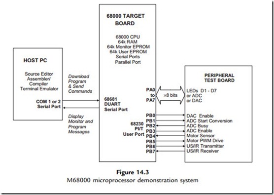
A typical development and training system based on the M68000 is shown in Figure 14.3. The target board incorporates separate CPU, EPROM, RAM and port chips. It can be connected to an applications board, which has a range of peripheral transducers, such as switches,

light-emitting diodes (LEDs) and a pulse width modulation (PWM)-controlled motor and shaft opto-sensor. This is controlled by the 68000 CPU via a standard 68230 parallel interface/ timer (PI/T) chip, which has three 8-bit ports, of which port A provides data transfer and port B the individual control and data lines. The operation of this type of system is described further in Appendix C, Section C.9.

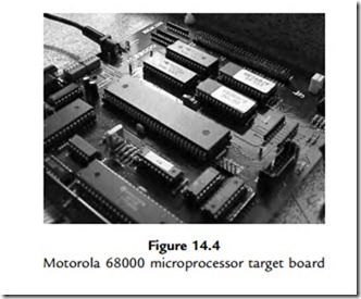
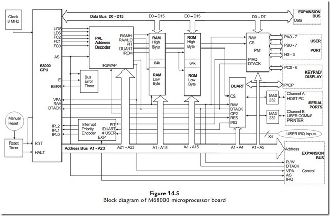
The M68000 target board is shown in Figure 14.4, with a block diagram of the system in Figure 14.5, which can be compared with the PIC internal architecture. Notice that in the PIC MCU block diagram, the internal architecture of the processor is visible, whereas in the

PIC Microcontrollers-1338

68000 system, it is concealed within the CPU. To design a microprocessor system, the CPU signal timing specification must be carefully studied, but this is not necessary in the microcontroller system, a major advantage of designing around an MCU. Another is that the microcontroller can be simulated as a whole, whereas in the microprocessor

PIC Microcontrollers-1339

PIC Microcontrollers-1340PIC Microcontrollers-1341

system only the CPU can be modeled, unless a system simulator such as Proteus VSM is used.

M68000 Program

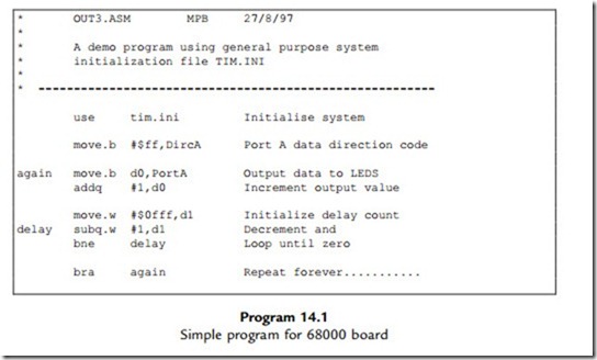
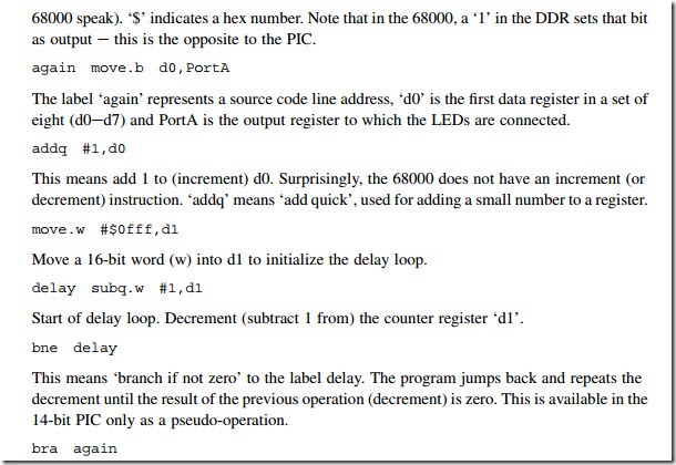
A simple program for the 68000 system is shown in Program 14.1, so that the syntax for a complex instruction set (CISC) processor can be compared with PIC assembly language. The program has a similar function to the PIC program BIN2, outputting a binary count to LEDs with a delay. The syntax is analyzed below.

Comments

The comments are delimited with a star.

use tim.ini

This is equivalent to the include directive in the PIC e it incorporates a file ‘tim.ini’ which contains standard register labels, PortA and DircA. Port A is the 8-bit port data register and DircA the data direction register (DDR).

move.b #$ff,DircA

Move the literal FF into the DDR to set all bits as output. The ‘.b’ means this is a byte operation (16- and 32-bit words can be moved in the 68000). ‘#’ means this is a literal (immediate data in

PIC Microcontrollers-1342

This is an unconditional jump equivalent to the GOTO label in PIC programs, to make the program repeat endlessly.

It can be seen that the 68000 syntax is more complex because, first, there are more instructions and, second, there are more registers and addressing modes.