Microprocessor Systems
The main elements of the microcontroller were originally developed as separate devices before being integrated into one chip to produce the microcontroller. The PC, as outlined in Chapter 1, is an example, where the individual central processing unit (CPU), memory and I/O devices are linked together by system address, data and control buses. The M68000 CPU was used in many different microprocessor systems from the 1980s onwards, including home computers, training systems, industrial controllers and instrumentation. It was the first, and most popular, 16-bit microprocessor. The original Apple® Macintosh®, main rival to the Intel-based PC, was designed around it.
The advantage of the conventional microprocessor system is that it can be designed to suit the application more precisely. It includes only those peripherals that are actually needed, and memory capacity as required. Obviously, the system is more complex to design and build, and so this type of system tends to be used for larger applications, where for example, extensive data storage is required. Although now largely obsolete, the 68000 remains a useful example of conventional CISC system architecture, because its regular architecture makes it easier to understand than current microprocessors which have a multi-level bus hierarchy and advanced design features added to the original CPU to improve performance.
M68000 Hardware
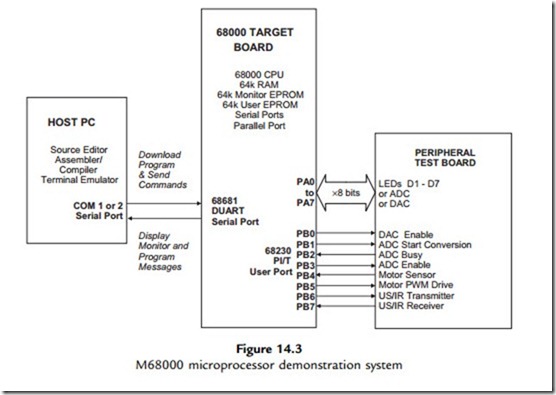
A typical development and training system based on the M68000 is shown in Figure 14.3. The target board incorporates separate CPU, EPROM, RAM and port chips. It can be connected to an applications board, which has a range of peripheral transducers, such as switches,
light-emitting diodes (LEDs) and a pulse width modulation (PWM)-controlled motor and shaft opto-sensor. This is controlled by the 68000 CPU via a standard 68230 parallel interface/ timer (PI/T) chip, which has three 8-bit ports, of which port A provides data transfer and port B the individual control and data lines. The operation of this type of system is described further in Appendix C, Section C.9.
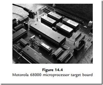
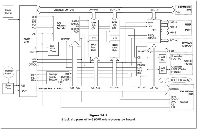
The M68000 target board is shown in Figure 14.4, with a block diagram of the system in Figure 14.5, which can be compared with the PIC internal architecture. Notice that in the PIC MCU block diagram, the internal architecture of the processor is visible, whereas in the
68000 system, it is concealed within the CPU. To design a microprocessor system, the CPU signal timing specification must be carefully studied, but this is not necessary in the microcontroller system, a major advantage of designing around an MCU. Another is that the microcontroller can be simulated as a whole, whereas in the microprocessor
system only the CPU can be modeled, unless a system simulator such as Proteus VSM is used.
M68000 Program
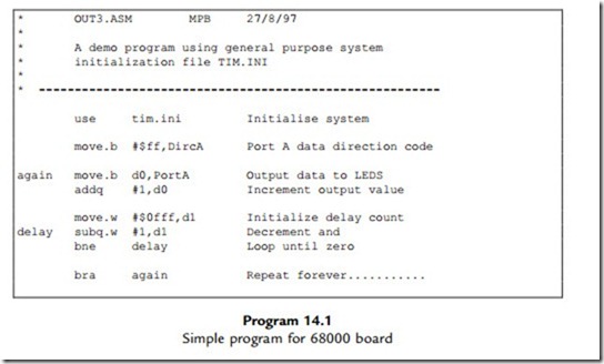
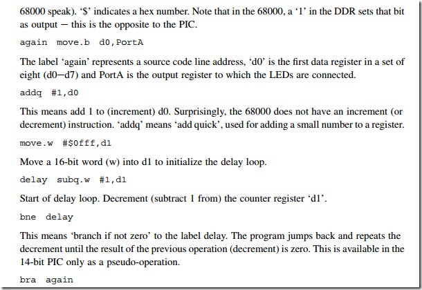
A simple program for the 68000 system is shown in Program 14.1, so that the syntax for a complex instruction set (CISC) processor can be compared with PIC assembly language. The program has a similar function to the PIC program BIN2, outputting a binary count to LEDs with a delay. The syntax is analyzed below.
Comments
The comments are delimited with a star.
use tim.ini
This is equivalent to the include directive in the PIC e it incorporates a file ‘tim.ini’ which contains standard register labels, PortA and DircA. Port A is the 8-bit port data register and DircA the data direction register (DDR).
move.b #$ff,DircA
Move the literal FF into the DDR to set all bits as output. The ‘.b’ means this is a byte operation (16- and 32-bit words can be moved in the 68000). ‘#’ means this is a literal (immediate data in
This is an unconditional jump equivalent to the GOTO label in PIC programs, to make the program repeat endlessly.
It can be seen that the 68000 syntax is more complex because, first, there are more instructions and, second, there are more registers and addressing modes.
