SYSTEM TIME RESPONSE CHARACTERISTICS:TIME RESPONSE COMPARISON

In this chapter we investigate the time response of a sampled data system and compare it with the response of a similar continuous system. In addition, the mapping between the s-domain and the z-domain is examined, the important time response characteristics of continuous systems are revised and their equivalents in the discrete domain are discussed.

TIME RESPONSE COMPARISON

An example closed-loop discrete-time system with a zero-order hold is shown in Figure 7.1(a). The continuous-time equivalent of this system is also shown in Figure 7.1(b), where the sampler (A/D converter) and the zero-order hold (D/A converter) have been removed. We shall now derive equations for the step responses of both systems and then plot and compare them.

As described in Chapter 6, the transfer function of the above discrete-time system is given by

System Time Response Characteristics-0055

System Time Response Characteristics-0056

System Time Response Characteristics-0057


SAMPLED DATA SYSTEMS AND THE Z-TRANSFORM:THE z-TRANSFORM

THE z-TRANSFORM

Equation (6.7) defines an infinite series with powers of esnT . The z-transform is defined so that

SNAG-0180

i.e. the r (nT ) are the coefficients of this power series at different sampling instants.

The z-transformation is used in sampled data systems just as the Laplace transformation is used in continuous-time systems. The response of a sampled data system can be determined easily by finding the z-transform of the output and then calculating the inverse z-transform,

Sampled Data Systems and the z-Transform-0019

Sampled Data Systems and the z-Transform-0020Sampled Data Systems and the z-Transform-0021

Sampled Data Systems and the z-Transform-0022

Tables of z-Transforms

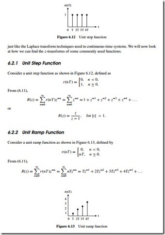
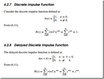
A table of z-transforms for the commonly used functions is given in Table 6.1 (a bigger table is given in Appendix A). As with the Laplace transforms, we are interested in the output response y(t ) ofa system and we must find the inverse z-transform to obtain y(t ) from Y (z).

The z-Transform of a Function Expressed as a Laplace Transform It is important to realize that although we denote the z-transform equivalent of G(s) by G(z), G(z) is not obtained by simply substituting z for s in G(s). We can use one of the following methods to find the z-transform of a function expressed in Laplace transform format:

• Given G(s), calculate the time response g(t ) by finding the inverse Laplace transform of G(s).

Then find the z-transform either from the first principles, or by looking at the z-transform tables.

• Given G(s), find the z-tranform G(z) by looking at the tables which give the Laplace trans- forms and their equivalent z-transforms (e.g. Table 6.1).

• Given the Laplace transform G(s), express it in the form G(s) = N (s)/D(s) and then use the following formula to find the z-transform G(z):

Sampled Data Systems and the z-Transform-0023Sampled Data Systems and the z-Transform-0024

Method 2: By using the z-transform transform tables for the partial product. From Table 6.1, the z-transform of 1/(s + a) is z/(z eaT ). Therefore the z-transform of (6.16) is

Sampled Data Systems and the z-Transform-0025

Sampled Data Systems and the z-Transform-0026

Sampled Data Systems and the z-Transform-0028

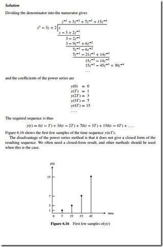
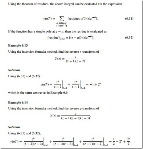
The inverse z-transform is obtained in a similar way to the inverse Laplace transforms. Gener- ally, the z-transforms are the ratios of polynomials in the complex variable z, with the numerator polynomial being of order no higher than the denominator. By finding the inverse z-transform we find the sequence associated with the given z-transform polynomial. As in the case of inverse Laplace transforms, we are interested in the output time response of a system. There- fore, we use an inverse transform to obtain y(t ) from Y (z). There are several methods to find the inverse z-transform of a given function. The following methods will be described here:

• power series (long division);

• expanding Y (z) into partial fractions and using z-transform tables to find the inverse transforms;

• obtaining the inverse z-transform using an inversion integral.

Given a z-transform function Y (z), we can find the coefficients of the associated sequence y(nT )at the sampling instants by using the inverse z-transform. The time function y(t ) is then determined as

Sampled Data Systems and the z-Transform-0029

Solution

Dividing the denominator into the numerator gives

Sampled Data Systems and the z-Transform-0030

Sampled Data Systems and the z-Transform-0031

Method 2: Partial fractions. Similar to the inverse Laplace transform techniques, a partial fraction expansion of the function Y (z) can be found, and then tables of known z-transforms can be used to determine the inverse z-transform. Looking at the z-transform tables, we see that there is usually a z term in the numerator. It is therefore more convenient to find the partial fractions of the function Y (z)/z and then multiply the partial fractions by z to obtain a z term in the numerator.

Sampled Data Systems and the z-Transform-0032

Sampled Data Systems and the z-Transform-0033

The process of finding inverse z-transforms is aided by considering what form is taken by the roots of Y (z). It is useful to distinguish the case of distinct real roots and that of multiple order roots.

Sampled Data Systems and the z-Transform-0034

Sampled Data Systems and the z-Transform-0034Sampled Data Systems and the z-Transform-0035Sampled Data Systems and the z-Transform-0036Sampled Data Systems and the z-Transform-0037


SAMPLED DATA SYSTEMS AND THE Z-TRANSFORM:THE SAMPLING PROCESS

A sampled data system operates on discrete-time rather than continuous-time signals. A digital computer is used as the controller in such a system. A D/A converter is usually connected to the output of the computer to drive the plant. We will assume that all the signals enter and leave the computer at the same fixed times, known as the sampling times.

A typical sampled data control system is shown in Figure 6.1. The digital computer performs the controller or the compensation function within the system. The A/D converter converts the error signal, which is a continuous signal, into digital form so that it can be processed by the computer. At the computer output the D/A converter converts the digital output of the computer into a form which can be used to drive the plant.

THE SAMPLING PROCESS

A sampler is basically a switch that closes every T seconds, as shown in Figure 6.2. When a continuous signal r (t ) is sampled at regular intervals T , the resulting discrete-time signal is shown in Figure 6.3, where q represents the amount of time the switch is closed.

In practice the closure time q is much smaller than the sampling time T , and the pulses can be approximated by flat-topped rectangles as shown in Figure 6.4.

In control applications the switch closure time q is much smaller than the sampling time T and can be neglected. This leads to the ideal sampler with output as shown in Figure 6.5.

The ideal sampling process can be considered as the multiplication of a pulse train with a continuous signal, i.e.

Sampled Data Systems and the z-Transform-0012

Sampled Data Systems and the z-Transform-0013

Sampled Data Systems and the z-Transform-0014

Sampled Data Systems and the z-Transform-0015

Sampled Data Systems and the z-Transform-0016

A sampler and zero-order hold can accurately follow the input signal if the sampling time T is small compared to the transient changes in the signal. The response of a sampler and a zero-order hold to a ramp input is shown in Figure 6.9 for two different values of sampling period.

Sampled Data Systems and the z-Transform-0017

Sampled Data Systems and the z-Transform-0018


MICROCONTROLLER PROJECT DEVELOPMENT:PROGRAM DEVELOPMENT TOOLS

PROGRAM DEVELOPMENT TOOLS

Historically, modular programming has been accepted as a good software design concept. Also known as structured programming, a software task is divided into smaller manageable tasks where each task is a self-contained piece of code, also called a module. Modules are

then designed using well-known constructs for sequence, selection and iteration. Although a structured approach to programming does not guarantee that a program will be free of errors, it helps to minimize the design errors and makes the final code much more readable and maintainable.

There are many tools available to help the programmer in the development and design of good programs. Some popular tools are: flow charts, structure charts, Unified Modeling LangaugeTM, Nassi–Schneidermann diagrams, Ferstl diagrams, Hamilton–Zeldin diagrams, and pseudocode. In this section we shall only look at some of the commonly used tech- niques. Further detailed information can be obtained from most books and papers on computer science.

Flow Charts

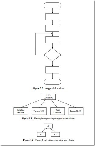
Flow charts have been around since the early days of programming. These type of charts are only useful for small applications. One of the disadvantages of flow charts is that the drawing and modifying the diagrams can be very time- consuming. Flow charts also have the disadvantage that they tend to produce unstructured code which is very difficult to maintain. A typical flow chart is shown in Figure 5.2.

Structure Charts

Structure charts, also known as Jackson structured programming tools, were developed in the 1970s by Michael Jackson and became a widely used software design tool, especially in Europe.

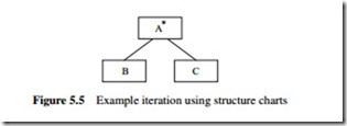
Structure charts are similar to flow charts but are easier to draw and modify. Structure charts also tend to produce well-structured code which is easy to understand and maintain. The three basic operations of sequence, selection and iteration are shown differently using structure charts.

Sequence

Sequence is shown with rectangles drawn next to each other. The sequence of operations is from left to right. An example is given in Figure 5.3 where first the I/O port is initialized, then the LED is turned on, and finally the LED is turned off aftera5s delay.

Selection

Selection is shown by placing a small circle at the top right-hand side of a rectangle. An example is given in Figure 5.4 where if condition1 is true then process B is performed, and if condition2 is true process C is performed.

Microcontroller Project Development-0001

Microcontroller Project Development-0002

Iteration

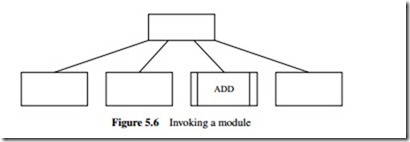
Iteration is shown by placing an asterisk sign at the top right-hand side of a rectangle. An example is given in Figure 5.5 where processes B and C are repeated.

Invoking Modules

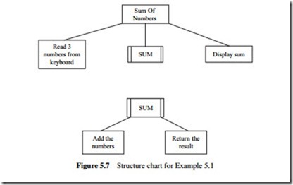
In structure charts modules can be shown with double-sided rectangles. An example is shown in Figure 5.6 where module ADD is called.

Example 5.1

Draw the structure chart for an application where three numbers are read from the keyboard into a main program, their sum calculated using a module called SUM, and the result displayed by the main program.

Solution

The structure chart for this example is shown in Figure 5.7.

Pseudocode

One of the disadvantages of graphical design methods such as flow diagrams and structure charts is that it can take a long time to draw them and that it is not easy to modify them.

Pseudocode is a kind of structured English for describing the operation of algorithms. It allows the programmer to concentrate on the development of the algorithm independent

Microcontroller Project Development-0003

Microcontroller Project Development-0004

of the details of the target language. There are no fixed rules or standards for developing pseudocode, and individual designers may have their own personal style of pseudocode. There are, however, guidelines to help the designer develop readable and powerful pseudocode. Pseudocode is based on the concept that any program consists of three major items: sequencing, selection, and iteration. Pseudocode is then developed using English sentences to describe algorithms, and this code cannot be compiled. If a program consists of a number of modules called by the main program then each module should be described using pseudocode. A brief description of the verbs and sentences that can be used in pseudocode is given in the rest of this section.

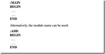
BEGIN–END

This construct is used to declare the beginning and end of a program or module. Keywords such as ‘:MAIN’ can be used before BEGIN to declare the beginning of the main program:

Microcontroller Project Development-0005

As shown in these examples, the lines should be indented to make the algorithm easier to read.

Sequencing

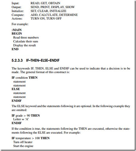
A sequence is a linear progression where the tasks are performed sequentially one after the other. Each action should be written on a new line and all the actions should be aligned with the same indent. The following keywords can be used for the description of the algorithm:

Microcontroller Project Development-0006Microcontroller Project Development-0007

Microcontroller Project Development-0008

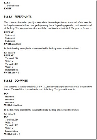
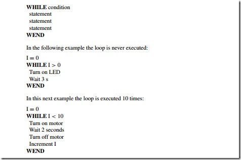
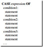
The CASE construct is used for multi-way branch operations. An expression is selected and, based on the value of this expression, a number of mutually exclusive tests can be done and statements can be executed for each case. The general format of this construct is:

Microcontroller Project Development-0009

Microcontroller Project Development-0010

Invoking Modules

Modules can be called using the CALL keyword and then specifying the name of the module. It is useful if the input parameters to be passed to the module are specified when a module is called. Similarly, at the header of the module description the input and the output parameters of a module should be specified. An example is given below.

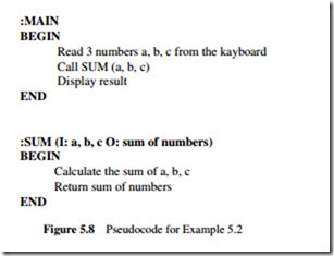
Example 5.2

Write the pseudocode for an application where three numbers are read from the keyboard into a main program, their sum calculated using a module called SUM, and the result displayed by the main program.

Solution

The pseudocode for the main program and the module are given in Figure 5.8.

Microcontroller Project Development-0011


MICROCONTROLLER PROJECT DEVELOPMENT:HARDWARE AND SOFTWARE REQUIREMENTS

HARDWARE AND SOFTWARE REQUIREMENTS

The development of a microcontroller based project requires hardware and software products. Hardware requirements generally depend on how complex the project is, but the following hardware products are normally required in almost all types of projects:

• microcontroller programmer;

• microcontroller development board or breadboard with the required components;

• microcontroller chips;

• PC;

• test equipment such as a voltmeter, logic pulser or oscilloscope.

Figure 5.1 shows the basic hardware requirements. A microcontroller programmer is connected to a PC and is used to download the user program to the target microcontroller program memory. For flash type program memories no additional hardware is normally required. The development of systems based on EPROM type program memories requires an EPROM eraser device so that the microcontroller program memory can be erased and reprogrammed.

Small projects incorporating simple LEDs and buzzers can be developed using microcon- troller development boards. These boards usually have built-in LEDs, switches, buzzers, etc. so that the user can test programs with simple to moderate complexity. Some development boards also incorporate chip programmer hardware so that the target microcontroller can be programmed on the same board. Complex projects can initially be built and tested on a bread- board. If the project is to be used in commercial or in industrial applications, then a printed circuit board design of the project is created.

A PC is required mainly for two purposes during the development of a microcontroller based project: the user program is developed and compiled on the PC, and the PC is used to transfer the user object code to the device programmer so that the program memory of the target microcontroller can be loaded with the user program.

Depending upon the complexity of the project, several types of test equipment may be required. For simple projects a voltmeter may be sufficient to test the static voltage levels around the circuit. For more complex projects, a logic analyser, logic pulser, frequency counter, or an oscilloscope may be required.

Microcontroller Project Development-0000

In addition to the above hardware, a number of software products will be required during the development of a microcontroller based product. The minimum required software is:

• program development software;

• microcontroller assembler (or compiler if a high-level language is used);

• microcontroller device programmer software.

Program development software, or an editor, is required to write the program code. Most assemblers or compilers provide built-in editors and the user programs can be developed using these editors.

Once a program is written it has to be assembled or compiled if a high-level language is used. The object code is normally produced from the assembler or the compiler if the program contains no errors.

A microcontroller device programmer software is then required to transfer the object code to the program memory of the target microcontroller.

Depending on the complexity of the project, additional software products, such as simu- lators, debuggers or in-circuit emulators, can be used to test and verify the operation of a program.

Simulator programs are run on a PC and can be used without any project hardware. Simulators are extremely useful in single-stepping and testing the user programs before the program is loaded into the target hardware. Debuggers are similar to simulators, and some debuggers require the code to be loaded into the target microcontroller. The user can insert break-points using debuggers and then test the flow of data and control in a program.

In-circuit emulators can be used in complex projects. Using an emulator, the user can test a program very easily on the target hardware by inserting break-points, and by single-stepping using the target hardware. Although the in-circuit emulators can be very useful, they are usually very expensive.


PROGRAMMING PIC MICROCONTROLLERS IN C:PIC MICROCONTROLLER INPUT–OUTPUT INTERFACE

PIC MICROCONTROLLER INPUT–OUTPUT INTERFACE

A microcontroller communicates with the outside world using its input–output ports. These ports can be analog or digital. Analog ports are used to read data from analog devices, e.g. the voltage across a resistor. Digital ports are used to read data from digital devices, e.g. the state of a switch. Microcontroller outputs are usually connected to LEDs, LCDs, buzzers, seven- segment displays and similar devices. The input can be a push-button switch, a keyboard or a similar device.

PIC microcontroller output ports can source and sink 25 mA of current. When an output port is sourcing current, the current flows out of the port pin. Similarly, when an output port is sinking current, the current flows towards the output pin. Devices such as LEDs, LCDs and other small devices which operate with up to 25 mA can be connected to the microcontroller output ports. Devices which require larger currents can be connected to the microcontroller ports by using a transistor switch to increase the current capability of the port pin.

Connecting an LED

Most LEDs operate with about 2V and they draw about 10 mA from the power supply. An LED can be connected to the output port of the PIC microcontroller by using a series current limiting resistor, as shown in Figure 4.3.

Assuming the output voltage Vo of the port pin is +5 V when it is at logic 1, the value of the

Programming-PIC-Microcontrollers-in-[5]

An LED is connected to bit 0 of port B (i.e. pin RB0) of a PIC16F84 microcontroller. Write a program to flash the LED at 100 ms intervals. The hardware set-up is shown in Figure 4.4, where the microcontroller is operated with a 4 MHz crystal.

Programming-PIC-Microcontrollers-in-[17]

Programming-PIC-Microcontrollers-in-[16]

Connecting a push-button switch

A push-button switch is an input to the microcontroller. The simplest way to connect a switch is to connect the switch to one of the port pins of the microcontroller and pull up the port pin to the supply voltage +V using a resistor. The port pin is thus normally at logic 1 level. When

the switch is pressed the port pin can be shorted to ground to make the input go to logic 0. An example is given below.

Example 4.7

An LED is connected to bit 0 of port B (i.e. pin RB0) of a PIC16F84 microcontroller. Also, a push-button switch is connected to bit 7 of port B (i.e. pin RB7) using a resistor. Write a program which will turn ON the LED when the switch is pressed. The hardware set-up is shown in Figure 4.6.

Solution

The required program is given in Figure 4.7. At the beginning of the program port pin RB0 is configured as an output and port pin RB7 is configured as an input (bit pattern

Programming-PIC-Microcontrollers-in-[6]

10000000 = 0 × 80 is sent to TRISB register). The state of the switch is then checked continuously and as soon as the switch is pressed the LED is turned on.

Connecting an LCD

LCD displays are commonly used in microcontroller based systems to display the value of a variable, to prompt the user for data, or to give information to the user. LCDs can either be text based or graphical. Text based LCDs are used in most microcontroller applications. These LCDs are easier to program and their costs are much lower than graphical displays.

One of the most popular LCD displays is based on a controller known as the HD44780. There are several models of LCDs using this controller:

LM016L 2 rows × 16 characters per row LM017L 2 rows × 20 characters per row LM018L 2 rows × 40 characters per row LM044L 4 rows × 20 characters per row  The programming of an LCD is generally a complex task and the programmer needs to know the internal operations of the LCD controller. Fortunately, the PICC language supports the HD44780 type LCDs and any data can easily be displayed on an LCD using simple function calls. The following functions are available:

Programming-PIC-Microcontrollers-in-[27]

HD44780 type LCDs normally have 14 pins. Table 4.2 shows the pin numbers and the function of each pin. Pin 3 is used to control the contrast of the display. Typically this pin is connected to the supply voltage using a potentiometer, and the contrast is changed by moving the arm of the potentiometer. The RS pin is used to send a control message or a text message to the LCD. When the R/W pin is at logic 0, a command or a text message can be sent to the LCD, and this is the normal operating mode. When R/W is at logic 1, the LCD status can be read. The LCD is enabled when the E pin is at logic 0. Pins D0 to D7 are the data inputs. The LCD can either be used in full 8-bit mode, or in 4-bit half mode where only the upper four data pins are used. In most applications the 4-bit mode is selected since it uses fewer pins and frees the microcontroller input–output pins. The PICC language configures the LCD in 4-bit mode.

In order to use the above LCD functions, an LCD must be connected in a certain way to the microcontroller port pins. The default connection is:

Programming-PIC-Microcontrollers-in-[25]

Programming-PIC-Microcontrollers-in-[13]

Solution

clip_image0083_thumbThe program listing is shown in Figure 4.9. At the beginning of the program ports A and B are configured as outputs. Then the LCD is initialized and the string ‘CONTROL’ is sent to the LCD using the command lcd puts.

A more complex microcontroller example using an analog temperature sensor, an A/D converter and an LCD is given below.

Example 4.9

An LM35DZ type analog temperature integrated circuit is connected to analog input AN0 (or RA0) of a PIC16F877 microcontroller. Also, an LCD is connected to the microcontroller as shown in Figure 4.10. Write a program to display the ambient temperature every second on

the LCD. The display should show the temperature as ‘TEMP = nn’, where nn is the ambient

temperature. This is an example of a digital thermometer.

Programming-PIC-Microcontrollers-in-[29]

Programming-PIC-Microcontrollers-in-[18]

The program listing of the digital thermometer is given in Figure 4.11. At the beginning of the program bit 0 of port A is configured as input and port B is configured as output. Then,

ADCON1 register is configured (see Chapter 3) by sending the bit pattern ‘10001110 = 0 ×

8E’, so that the RA0 port pin is analog, and the RA2 and RA3 port pins are digital. Also, bit 7 (ADFM) of ADCON1 is set to 1 so that the 8 bits of the converted data will be in the register ADRESL and the upper 2 bits will be in bits 0 and 1 of the register ADRESH. The A/D converter clock is chosen as fosc/8 and channel 0 of the A/D converter is selected by configuring the ADCON0 register.

The A/D converter is started by setting bit 2 of the ADCON0 register (sending 0 × 45 to

clip_image017_thumbADCON0). The program then waits (using a while loop) for the completion of the conversion. At the end of the conversion bit 2 of ADCON0 is cleared by the microcontroller and this is sensed by the program. The program then exits the while loop and reads the lower and upper bytes of the converted 10-bit data, combines the data into a single variable called temp, and then converts the data into real value, i.e. millivolts. The actual temperature in degrees Celsius is then obtained by dividing this voltage by 10. The temperature is then converted into a string called tempc and is sent to the LCD display using the lcd puts command. The program clears

Programming-PIC-Microcontrollers-in-[10]

clip_image0072_thumbclip_image022_thumbthe LCD display and repeats continuously after 1 s delay. The delay is created by using a function called wait a second. The program displays the temperature as TE M P = nn where nn is the ambient temperature.

Notice that the program uses the header files <pic.h>, <delay.c>, <lcd.c>, and <stdio.h>. The file <pic.h> contains the PIC microcontroller definitions. <delay.c> is used to create delays in the program. <lcd.c> is used for the LCD initialization and control functions. Finally, <stdio.h> is used to convert an integer into a string so that it can be displayed on the LCD.


Programming Microcontrollers In C:Program Description Language (PDL)

Program Description Language (PDL)

There are many methods that a programmer may choose to describe the algorithm to be implemented by a program. Flow charts have been used extensively in the past in many computer programming tasks. Although flow charts are useful, they tend to create an unstructured code and also a lot of time is usually wasted drawing them, especially when developing complex programs. In this section we shall be looking at a different way of describing the operation of a program, namely by using a program description language (PDL).
A PDL is an English-like language which can be used todescribe the operation of a program. Although there are many variants of PDL, we shall be using simple constructs of PDL in our programming exercises, as described below.

START-END

Every PDL program (or sub-program) should start with a START statement and terminate with an END statement. The keywords in a PDL code should be highlighted in bold to make the code more clear. It is also good practice to indent program statements between the PDL keywords.

Programming-Microcontrollers-in-C-00

Programming-Microcontrollers-in-C-00[4]

Sequencing

For normal sequencing in a program, write the steps as short English text as if you are describing the program.

Example:

Turn on the valve Clear the buffer Turn on the LED

IF-THEN-ELSE-ENDIF

Use IF, THEN, ELSE, and ENDIF statements to describe the flow of control in your programs.

Programming-Microcontrollers-in-C-00[2]

REPEAT-UNTIL

This is another useful control construct which can be used in PDL codes. An example is shown below where the program waits until a switch value is equal to1.

REPEAT

Turn on buzzer Read switch value

UNTIL switch = 1


Programming Microcontrollers In C:Structure of a Microcontroller-based C Program

Structure of a Microcontroller-based C Program

The structure of a C program developed for a microcontroller is basically the same as the structure of a standard C program, with a few minor changes. The structure of a typical microcontroller-based C program is shown in Fig. 2.1. It is always advisable to describe the project at the beginning of a program using comment lines. The project name, filename, date, and the target processor type should also be included in this part of the program. The register definition file should then be included for the type of target processor used. This file is supplied as part of the compiler and includes the definitions for various registers of the microcontroller. In the example in Fig. 2.1, the register definition file for the Atmel 89C2051 type microcontroller is included. The global definitions of the variables used should then be entered, one line for each definition. The functions used in the program should then be included with the appropriate comments added to the heading and alsotoeach line of the

Programming-Microcontrollers-in-C-00

functions. The main program starts with the keyword main(), followed by the opening brackets ‘{‘. The lines of the main program should also contain comments to clarify the operation of the program. The program is terminated by a closing bracket ‘}’.

An example program is shown in Fig. 2.2. This program receives an 8-bit data from port 1 of an 89C2051 type microcontroller. The state of a switch, connected to bit 0 of port 3, is then checked. If the switch is 1, the value of the data is doubled by calling function double_it. If, on the other hand, the state of the switch is 0, the data value is incremented by 2 by calling function inc_by2, and then the program stops. It is important to realize that there is no returning point in a microcontroller program. Thus, where necessary, an endless loop should be formed at the end to stop the program from going into undefined parts of its code memory.


Programming Microcontrollers In C

The C programming language is a general-purpose high-level programming language that offers efficient and compact code and provides elements of structured programming. Many control and monitoring-based applications can be solved more efficiently with C than with any other programming language. C was originally available on mainframe computers, mini- computers, and personal computers (PCs). The C programming language is now available on most microcontrollers and microprocessors.

This book is not intended for teaching the C programming language. It is assumed that the reader is familiar with programming in C. The aim of this chapter is to show the special features of the C language when programming microcontrollers. In this book, the industry standard C51 optimizing C compiler is used throughout. This compiler has been developed by Keil Elektronik GmbH. C51 is available on both MS-DOS and Windows-based operating systems and the compiler implements the American National Standards Institute (ANSI) standard for the C language.

There are many other high-level language compilers available for micro- controllers, including PASCAL, BASIC, and other C compilers. Some of these compilers are freely available as shareware products and some can be obtained from the Internet with little cost. Also, some companies supply free limited capability compilers, mainly for evaluation purposes. These compilers can be used for learning the features of a specific product and in some cases small projects can be developed with such compilers. Section 2.5 gives a list of some sites where readers can find more information on high-level microcon- troller compilers.

The C51 compiler has been developed for the 8051 family of microcontrollers. This is one of the most commonly used industry standard C compilers for the 8051 family, and can generate machine code for most of the 20-pin and 40-pin 8051 devices and its derivatives, including the following microcontrollers:

Intel and others 8051, 80C51, and 87C51

Atmel 89C51, 89C52, 89C55, 89S8252, and 89S53

Atmel 89C1051 and 89C2051

AMD 80C321, 80C521, and 80C541 Dallas 80C320, 80C520, and 80C530

Signetics 8xC750, 8xC751, and 8xC752

Siemens 80C517 and 80C537

C51 is a professional, industry standard compiler with many features, including a large number of built-in functions. In this chapter we shall be looking at the features of the C51 programming language as applied to programming single chip microcontrollers. More information on the C51 compiler is available from Keil Elektronik GmbH (see the C51 Optimizing 8051 Compiler and Library Reference Manual).


Rs232 Serial Communication Projects:A Simple Calculator Program Using the RS232 Port

PROJECT 24 – A Simple Calculator Program Using the RS232 Port

Function

This is a simple calculator project based upon the 89C51 type microcontroller. The microcontroller is connected to an RS232 serial terminal. The user can perform simple addition, subtraction, multiplication, and division of numbers using the microcontroller.

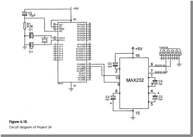
Circuit Diagram

This project is based upon the 89C51 microcontroller. This is a 40-pin device which is software compatible with the 89C2051 microcontroller. The 89C51 contains a 4 Kbyte flash program memory, 128 bytes of RAM, 32 program- mable input/output lines, and six interrupt sources.

The circuit diagram of this project is shown in Fig. 6.10. A 12 MHz crystal and two capacitors are connected to pins 18 and 19 of the microcontroller. Reset input is connected to a capacitor and a resistor. Transmit output (TXD) and receive input (RXD) of the device are connected to a MAX232 type RS232 converter IC. EA is the external program enable pin and this pin should be connected to +5 V for internal program executions.

Program Description

The program operates as a simple calculator. When power is applied to the microcontroller, a menu is displayed on the user’s terminal and the user is prompted toenter twonumbers and the operation tobe performed. A typical dialogue is given below (note that the characters typed by the user are underlined for clarity):

Rs232-Serial-Communication-Projects-[12]

Rs232-Serial-Communication-Projects-Rs232-Serial-Communication-Projects-[10]

Program Listing

The program listing is given in Fig. 6.11. The serial port is initialized by the function serial_init. The program then prints a heading and a menu using the built-in function printf. The user is prompted to enter the numbers and the operation to be performed. The first number is stored in variable numl using the built-in function scanf. The second number is stored in variable num2. The operation to be performed is stored in variable oper.A switch statement is then used to select the required operation. The result of the calculation is stored in variable result and this is then displayed using a printf function. The program repeats forever unless stopped by the user.

Components Required

The following components will be required for this project:

Rs232-Serial-Communication-Projects-[3]Rs232-Serial-Communication-Projects-[13]Rs232-Serial-Communication-Projects-[16]