PROGRAM DEVELOPMENT TOOLS
Historically, modular programming has been accepted as a good software design concept. Also known as structured programming, a software task is divided into smaller manageable tasks where each task is a self-contained piece of code, also called a module. Modules are
then designed using well-known constructs for sequence, selection and iteration. Although a structured approach to programming does not guarantee that a program will be free of errors, it helps to minimize the design errors and makes the final code much more readable and maintainable.
There are many tools available to help the programmer in the development and design of good programs. Some popular tools are: flow charts, structure charts, Unified Modeling LangaugeTM, Nassi–Schneidermann diagrams, Ferstl diagrams, Hamilton–Zeldin diagrams, and pseudocode. In this section we shall only look at some of the commonly used tech- niques. Further detailed information can be obtained from most books and papers on computer science.
Flow Charts
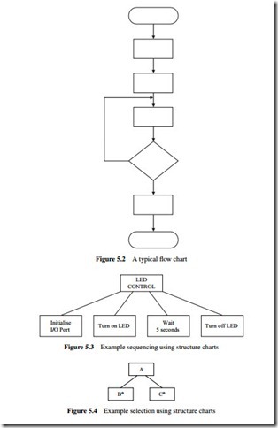
Flow charts have been around since the early days of programming. These type of charts are only useful for small applications. One of the disadvantages of flow charts is that the drawing and modifying the diagrams can be very time- consuming. Flow charts also have the disadvantage that they tend to produce unstructured code which is very difficult to maintain. A typical flow chart is shown in Figure 5.2.
Structure Charts
Structure charts, also known as Jackson structured programming tools, were developed in the 1970s by Michael Jackson and became a widely used software design tool, especially in Europe.
Structure charts are similar to flow charts but are easier to draw and modify. Structure charts also tend to produce well-structured code which is easy to understand and maintain. The three basic operations of sequence, selection and iteration are shown differently using structure charts.
Sequence
Sequence is shown with rectangles drawn next to each other. The sequence of operations is from left to right. An example is given in Figure 5.3 where first the I/O port is initialized, then the LED is turned on, and finally the LED is turned off aftera5s delay.
Selection
Selection is shown by placing a small circle at the top right-hand side of a rectangle. An example is given in Figure 5.4 where if condition1 is true then process B is performed, and if condition2 is true process C is performed.
Iteration
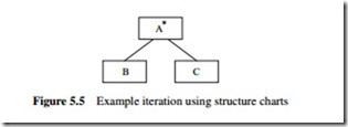
Iteration is shown by placing an asterisk sign at the top right-hand side of a rectangle. An example is given in Figure 5.5 where processes B and C are repeated.
Invoking Modules
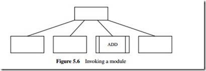
In structure charts modules can be shown with double-sided rectangles. An example is shown in Figure 5.6 where module ADD is called.
Example 5.1
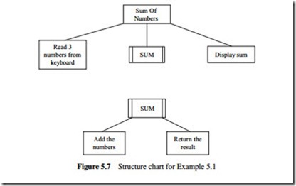
Draw the structure chart for an application where three numbers are read from the keyboard into a main program, their sum calculated using a module called SUM, and the result displayed by the main program.
Solution
The structure chart for this example is shown in Figure 5.7.
Pseudocode
One of the disadvantages of graphical design methods such as flow diagrams and structure charts is that it can take a long time to draw them and that it is not easy to modify them.
Pseudocode is a kind of structured English for describing the operation of algorithms. It allows the programmer to concentrate on the development of the algorithm independent
of the details of the target language. There are no fixed rules or standards for developing pseudocode, and individual designers may have their own personal style of pseudocode. There are, however, guidelines to help the designer develop readable and powerful pseudocode. Pseudocode is based on the concept that any program consists of three major items: sequencing, selection, and iteration. Pseudocode is then developed using English sentences to describe algorithms, and this code cannot be compiled. If a program consists of a number of modules called by the main program then each module should be described using pseudocode. A brief description of the verbs and sentences that can be used in pseudocode is given in the rest of this section.
BEGIN–END
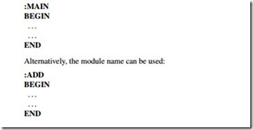
This construct is used to declare the beginning and end of a program or module. Keywords such as ‘:MAIN’ can be used before BEGIN to declare the beginning of the main program:
As shown in these examples, the lines should be indented to make the algorithm easier to read.
Sequencing
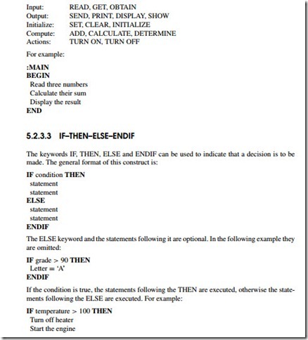
A sequence is a linear progression where the tasks are performed sequentially one after the other. Each action should be written on a new line and all the actions should be aligned with the same indent. The following keywords can be used for the description of the algorithm:
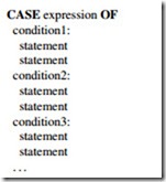
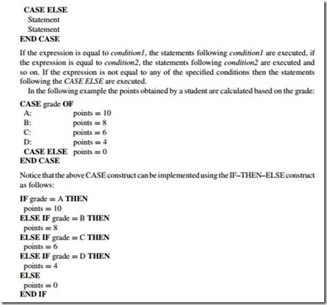
The CASE construct is used for multi-way branch operations. An expression is selected and, based on the value of this expression, a number of mutually exclusive tests can be done and statements can be executed for each case. The general format of this construct is:
Invoking Modules
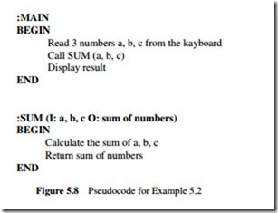
Modules can be called using the CALL keyword and then specifying the name of the module. It is useful if the input parameters to be passed to the module are specified when a module is called. Similarly, at the header of the module description the input and the output parameters of a module should be specified. An example is given below.
Example 5.2
Write the pseudocode for an application where three numbers are read from the keyboard into a main program, their sum calculated using a module called SUM, and the result displayed by the main program.
Solution
The pseudocode for the main program and the module are given in Figure 5.8.
