Introduction
Chapter 2 contained an extensive review of serial data communication concepts and the hardware and software that is built into the 8051 for enabling serial data transfers. Chapter 7 contained some brief programming examples of how this capability may be used. Serial data transmission has become so important to the overall computing strategy of industrial and commercial applications that a separate chapter on this crucial subject is appropriate.
One hallmark of contemporary computer systems is interconnectivity: the joining of computers via data networks that link the computers to each other and to shared resources, such as disk drives, printers, and other I/O devices. The beginning of the "computer age" saw isolated CPUs connected to their peripherals using manufacturer-specific data transmission configurations. One of the peripherals, however, was the teletype that had been borrowed from the telephone industry for use as a human interface to the computer, using the built-in keyboard and printer.
The teletype was designed to communicate using standard voice grade telephone lines via a modem (Modulator demodulator) that converts digital signals to analog frequencies and analog frequencies to digital signals. The data, by the very nature of telephone voice transmission, is sent and received serially. Various computer manufacturers adapted their equipment to fit the teletype, and, perhaps, the first "standard" interface in the industry was born.
This standard was enhanced in the early I 960’s with the establishment of an electrical/ mechanical specification for serial darn transmission that was assigned the number RS 232
by the Electronics Industry Association. A standard data code was also defined for all the characters in the alphahet, decimal numbers. punctuation marks. and control characters. Based on earlier telephonic codes. the standard hecame known as the American Standard Code for Information Interchange (ASC11).
The establishment of RS 232 and ASC11 coincided with the development of multiuser computer organizations wherein a number of users were Jinked to a host mainframe via serial data Jinks. By now. the CRT terminal had replaced the slower teletype. but the RS 232 serial plug remained, and serial data was encoded in ASCII. Peripheral devices, such as printers. adopted the same standards in order to access the growing market for serial devices.
Serial data transmission using ASC11 became so universal that specialized integrated circuits, Universal Asynchronous Receiver Transmitters (UARTS) were developed to perform the tasks of converting an 8-bit parallel data byte to a l0-bit serial stream and converting 10-bit serial data to an 8-bit parallel byte. When the second-generation 8051 microcontrollcr was designed. the UART became part of the circuit.
Chapter 7 introduced the basic programming concepts concerning transmitting and receiving data using the serial port of the 8051. In this chapter. we study the serial data modes available to the programmer and develop programs that use these modes. The four modes arc as follows:
Mode 0: Shift register mode
Mode I: Standard UART mode
Mode 2: Multiprocessor fixed mode
Mode 3: Multiprocessor variable mode
In this chapter, we also identify multiprocessor configurations that are appropriate for each mode and write sample programs to enable data communication between 8051 microcontrollers.
Network Configurations
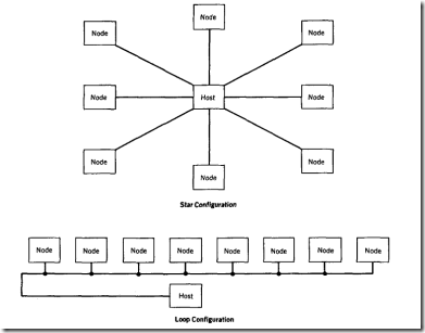
The first problem faced by the network system designer is how to physically hook the computers together. The two possible basic configurations are the star and the loop, which arc shown in Figure 9. 1.
The star features one line from a central computer to each remote computer, or from "host" to "node." This configuration is often used in time-sharing applications when a central mainframe computer is connected to remote terminals or personal computers using a dedicated line for each node. Each node sees only the data on its line; all communication is private from host to node.
The loop uses one communication line to connect all of the computers together. There may he a single host that controls all actions on the loop, or any computer may be enabled to he the host at any given time. The loop configuration is often used in data-gathering applications where the host periodically interrogates each node to collect the latest information about the monitored process. All nodes see all data; the communication is public between host and nodes.
Choosing the configuration to use depends upon many external factors that are often beyond the control of the system designer. Some general guidelines for selection are shown in the following table:
FIGURE 9.1 Communication Configurations
|
Objective |
Network |
Comments |
|
Reliability |
Star |
Single node loss per line loss |
|
Fault isolation |
Star |
Fault traceable to node and line |
|
Speed |
Star |
Each node has complete line use |
|
Cost |
Loop |
Single line for all nodes |
The star is a good choice when the number of nodes is small, or the physical distance from host to node is short. But, as the number of nodes grows, the cost and physical space represented by the cables from host to nodes begins to represent the major cost item in the system budget. The loop configuration becomes attractive as cost constraints begin to outweigh other considerations.
Microcontrollers are usually applied in industrial systems in large numbers distributed over long distances. Loop networks are advantageous in these situations, often with a host controlling data transmission on the loop. Host software is used to expedite fault
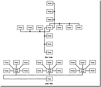
FIGURE 9.2 Hybrid Communication Configurations
and, thus, improve system reliability. High speed data transmission schemes can be employed to enhance system response time where necessary.
The old racing adage "Speed costs money: How fast do you want to go?" should be kept in mind when designing a loop system. Successors to RS 232, most notably RS 485, have given the system designer 100 kilobaud rates over 4000-foot distances using inexpensive twisted-pair transmission Jines. Faster data rates are possible at shorter distances, or more expensive transmission lines, such as coaxial cable, can be employed. Remember that wiring costs are often the major constraint in the design of large distributed systems.
Many hybrid network arrangements have evolved from the star and the loop. Figure 9. 2 shows two of the more popular types that contain features found in both basic configurations.

