8051 Data Communication Modes
The 8051 has one serial port-port pins 3.0 (RXD) and 3.1 (TXD)-that receives and transmits data. All data is transmitted or received in two registers with one name: SBUF. Writing to SBUF results in data transmission; reading SBUF accesses received data. Transmission and reception can take place simultaneously, and the receiver can be in the process of receiving a byte while a previous byte is still in SBUF. The first byte must be read before the reception is complete, or the second byte will be lost.
Physically the data is a series of voltage levels that are sampled, in the center of the bit period, at a frequency that is determined by the serial data mode and the program that controls that mode. All devices that wish to communicate must use the same voltage levels, mode, character code, and sampling frequency (baud rate). The wires that connect the ports must also have the same polarity so that the idle state, logic high, is seen by all ports.
The installation and checkout of a large distributed system are subject to violations of all of the "same" constraints listed previously. Careful planning is essential if cost and time overruns are to be avoided.
The four communication modes possible with the 8051 present the system designer and programmer with opportunities to conduct very sophisticated data communication networks.
Mode 0:Shift Register Mode
Mode 0 is not suitable for the interchange of data between 8051 microcontrollers. Mode 0 uses SBUF as an 8-bit shift register that transmits and receives data on port pin 3.0, while using pin 3.1 to output the shift clock. The data and the shift clock are synchronized using the six internal machine states, and even for microcontrollers using the same crystal frequency, they can be slightly out of phase due to differences in reset and start-up times.
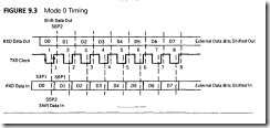
Figure 9.3 shows the timing for the transmission and reception of a data character.
Remember that the shift clock is generated internally and is always from the 8051 to the external shift register. The clock runs at the machine cycle frequency of fl l 2. Note that transmission is enabled any time SBUF is the destination of a write operation, regardless of the state of the transmitter empty flag, SCON bit l (T1).
Data is transmitted, LSB first, when the program writes to SBUF. Data is shifted right during S6P2, or 24/f seconds after the rising edge of the shift clock at S6PI. Data is stable from just after S6P2 for one cycle. Good design practice dictates that the data be shifted into the external shift register during the high-to-low transition of the shift clock, at S3Pl, to avoid problems with clock skew.
The receiver is enabled when SCON bit 5 (REN) is enabled by software and SCON bit 0 (RI) is set to 0. At the end of reception RI will set, inhibiting any form of character reception until reset by the software. The condition of RI cleared to 0 is unique for mode 0; all other modes are enabled to receive when REN is set without regard as to the state of RI. The reason is clear: Mode 0 is the only mode that controls when reception can take place. Enabling reception also enables the clock pulses that shift the received data into the receiver.
Reception begins, LSB first, with the data that is present during S5P2, or 24/f seconds before the rising edge of the shift clock at S6Pl. The incoming data is shifted to the right. Incoming data should be stable during the low state of the shift clock, and good design practice indicates that the data be shifted from the external shift register during the low-to-high transition of the shift clock, at S6Pl, so that the data is stable up to one clock period before it is sampled.
A serial data transmission interrupt is generated at the end of the transmission or reception of bit eight if enabled by the ES interrupt bit El.4 of the enable interrupt register. Software must reset the interrupting bit RI or T1. As the same physical pin is used for transmission and reception, simultaneous interrupts are not possible.
Mode 0 is well suited for rapid data collection and control of multi-point systems that use a simple two-wire system for data interchange. Multiple external shift registers can expand the external points to an almost infinite number. limited only by the response time desired for the application. For instance, at f = 16 megahertz, each point of a 10,000 point system could be monitored every 60 milliseconds. Common industrial systems do not require rates this high, and a reasonable rate of one point per second would leave adequate time for processing by the program.
Mode zero
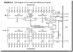
A small system that features 16 points of monitored data and 16 points of control is shown in Figure 9.4. Data from the process is converted from parallel to serial in the’ 166 type registers. Data to the process is converted from serial to parallel in the type ‘164 registers and latched into the ·373 latches.
It is important that the data be "frozen" before the shifting begins. The bits shifted in could be changed before reaching the microcontroller, or a control hit might be changed, momentarily, as it shifts through the output shift registers. Port pin 3.2 is used to disable the input registers from the process when high and to enable loading input values when low.
To read the inputs, P3.2 is brought high and the receiver is enabled (twice) to generate 16 input shift clocks. The high level on P3.2 prevents the shift clocks from reaching the output registers. At the end of the read, P3.2 is brought low to enable loading input values into the input registers. No clock pulses are generated, so the output control registers do not change state.
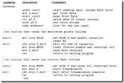
Control bits to the output registers are transmitted when P3.2 is low and SBUF has two data bytes written in succession. The two bytes generate 16 clock pulses that fill the output registers with the SBUF data. Port pin 3.3 is used to latch the newly shifted control data to the process by strobing the output data latches. A program that monitors and controls the points follows.
The program "mode zero" monitors 16 bits and controls the state of 16 bits. The system can be expanded indefinitely by expanding the shift register configurations shown in Figure 9.4. In this example program, whatever data is read on the monitored points is written to the control points. The direction of data flow to/from the 8051 is controlled by P3.2, (high = in). P3.3 latches new data to the process.
COMMENT
Note that in both the transmit and receive cases the interrupt bit must go high before the subroutine can be ended.
The data transmit and reception time is so short that interrupt-driven schemes are not efficient.
Mode 1: Standard 8-Bit UART Mode
In Chapter 7, several simple communication programs are studied that use the serial port configured as mode I, the standard UART mode normally used to communicate in 8-bit ASCII code. Only seven bits are needed to encode the entire set of ASCII characters. The eighth bit can be used for even or odd parity or ignored completely. Asynchronous data transmission requires a start and stop bit to enable the receiving circuitry to detect the start and finish of a complete character. A total of ten bits is needed to transmit the 7-bit ASCII character, as shown in Figure 9.5.
Transmission begins whenever data is written to SBUF. It is the responsibility of the programmer to ensure that any previous character has been transmitted by inspecting the TI bit in SCON for a set condition. Data transmission begins with a high-to-low start bit transition on TXD that signals receiving circuitry that a new character is about to arrive. The 8-bit character follows, LSB first and MSB parity bit last, and then the stop bit, which is high for one bit period. If another character follows immediately, a new start bit is signaled by a high-to-low transition; otherwise, the line remains high. The width of each transmitted data bit is controlled by the baud rate clock used. The receiver must use the same baud rate as the transmitter, or it reads the data at the wrong time in the character stream.
Reception begins if the REN bit is set in SCON and a high-to-low transition is sensed on RXD. Data bits are sampled at the baud rate in the center of the bit duration period. The received character is loaded into SBUF and the stop bit into SCON bit 2 (RBS) if the RI bit in SCON is cleared, indicating that the program has read the previous character; and either SM2 in SCON is cleared or SM2 is set and the received stop bit is high, which is the normal state for stop bits.
If these conditions are met, then SBUF is loaded with the received character, and RI is set. If the conditions are not met, the character is ignored, RI is not set, and the receive circuitry awaits the next start bit.
The restriction that a new character is not accepted unless RI is cleared seems reasonable. Data is lost if either the previous byte is overwritten or the new byte discarded, which is the action taken by the S05 l. The restriction on SM2 and the stop bit are not as obvious. Normally, SM2 will be set to 0, and the character will be accepted no matter what the state of the stop bit. Software can check RBS to ensure that the stop bit is correct before accepting the character if that is thought to be important.
Possible reasons for setting SM2 to force reception only when the stop bit is a I could be useful if the transmitter has the ability to change the stop bit from the normal high state. If the transmitter has this capability, then the stop bit can serve as an address bit in a multiprocessor environment where many loop microcontrollers are all receiving the same transmission. Only the microcontroller that has SM2 cleared can receive characters ending in either of the stop bit states. If all the microcontrollers but one have SM2 set, then all data transmissions ending in a low stop bit interrupt the unit with SM2 = O; the rest ignore the data. Transmissions ending in a high stop bit can interrupt all microcontrollers.
Transmitters with the capability to alter the stop bit state are not standard. The 8051 communication modes 2 and 3 use the SM2 bit for multiprocessing. Mode 1 is not needed for this use.
In summary, mode 1 should be used with SM2 cleared, as a standard S-bit UART, with software checks for proper stop bit magnitude if needed. As discussed in Chapter 7, the baud rate for modes 1 and 3 are determined by the overflow rate of timer 1, which is usually configured as an auto-reload timer. PCON bit 7 (SMOD) can double the baud rate when set.
Modeone
Mode 1 is most likely to be used in a dedicated system where the S05 I serial port is connected to a single similar port. A program that transmits and receives large blocks of data on an interrupt-driven basis is developed to investigate some problems common to data interchange programs.
To the main program, interrupt-driven communication routines are transparent: Data appears in RAM as it is received and disappears from RAM as it is transmitted. In both cases, the link between the main program and the interrupt-driven communication sub-routines are areas of RAM called buffers. These buffers serve to store messages that are to be sent and messages that are received.
Each buffer area is defined by two memory pointers. One pointer contains the address of the top of the huff er, or the location in RAM where the next character is to be stored, and the second contains the address of the next character to be read. The buffers are named "inbuf," for use in storing characters as they are received, and "outbuf’," for storing characters that are to be sent. The pointers to the tops of the buffers are named "intop" and "outop." respectively, while the pointers to the next character to be read are named "inplace " and "outplace."
The two buffers work in exactly the same way. The receive subroutine fills inbuf as characters are received and updates intop as it operates. The main program empties inbuf as it can and keeps inplace pointing to the next character to be read. The main program fills outbuf, while keeping outop updated to point to the next character to be stored. The transmission subroutine empties outbuf as it can and keeps outplace pointing to the next character to be read from outbuf,
These actions continue until the pointer to the top of the buffer equals the pointer to the next character. The buffer is now empty. and the pointers can be reset to the bottom of the buffer.
The buffer areas and pointers may be summarized as follows:
Outbuf: An area of RAM that holds characters to be transmitted
Outop: Pointer to outbuf that holds the address of the next character to be stored by the main program for transmission
Outplace: Pointer to outbuf that holds the address of the next character to he transmitted by the transmit subroutine
lnbuf: An area of RAM that holds received characters
Intop: Pointer to inbuf that holds the address of the next character received by the receive subroutine
lnplace: Pointer to inbuf that holds the address of the next character to be read by the main program
The main program and the transmit subroutine does not read data from a buffer whenever the place pointer equals the top pointer, which indicates that the buffer is empty.
The programmer has to make an estimate of how large the buffers need to be. Sometimes the general nature of the data is known when the system is in the design phase. The programmer(s) for the two computers that are communicating can define message length and frequency, arriving at a worst-case buffer size.
If the 8051 is part of a peripheral, such as a printer, that randomly receives large quantities of data, then the buffer size is fixed at an economic and competitive number using external RAM. For short and infrequent messages, internal RAM may suffice. In both cases, the receiving subroutine should have a means of communicating to the source of data when inbuf is becoming full so that the data flow can be suspended while inhuf is emptied. Our example program falls somewhere between these extremes; some external RAM will be needed, but not 32 kilobytes.
Registers RO and RI of register banks 0 and I are used effectively as pointers to the first 256d bytes of external RAM using MOVX instructions. For this example, the buffer sizes are fixed at I 28d bytes each, although there is no need for them to be of equal size. Larger buffers can be constructed using the DPTR.
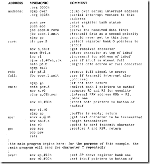
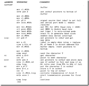
A program named "Modeone" handles communications between the 8051 and another computer using serial data mode I. Two I 28d byte buffers in external RAM store charac-ters to be transmitted or received. R0and R1 of register bank 0 keep track of data flow for the receive buffer inbuf, located in external RAM addresses 00h to 7Fh. R0and RI of register bank I serve the transmit buffer outbuf, external RAM addresses 80h to FFh. R0 is the place pointer, RI the top pointer to the buffers. The baud rate is set by timer I in the auto-reload mode to 1200 bits per second. Port pin 3.2 is set high when inbuf is I byte from a full condition.
cOMMENT
Note that the program has to initiate the first interrupt for the first character that is stored in a previously empty outbuf. If the first interrupt action were not done, transmission would never take place, as the T1 bit would remain a 0. The 0 state of the Tl bit is ambiguous: It can mean that the transmitter is busy sending a byte or that no activity is taking place at all. The 1 state of T1 is specific: A byte has been transmitted, and SBUF can receive the next byte.
The example program fills outbuf quickly, until outop rolls over to 00h. Outbuf is emptied until outplace rolls over also, and outbuf is re-initialized to BOh. Received data is always read before inbuf can fill up, as there is very little for the program to do. Adding a time delay in the program ensures that inbuf grows beyond one byte.
COMMENT
The data source should cease sending data to the 8051 until port 3.2 goes low. In this example, "full" is arbitrarily set at one byte below the maximum capacity of inbuf. The actual number for a full condition should be set at maximum capacity less the response time of the source expressed in characters.
No feedback from the source to the 8051 has been provided for halting transmission of data from the 8051. Feedback can be accomplished by using one of the INT lines as an input from the source to signal a full condition.
Modes 2 and 3: Multiprocessor
Modes 2 and 3 are identical except for the baud rate. Mode 2 uses a baud rate of f/32 if SMOD (PCON. 7) is cleared or f/64 if SMOD is set. For our 16 megahertz example, this results in baud rates of 500000 and 250000 bits per second, respectively. Pulse rates of these frequencies require care in the selection and installation of the transmission lines used to carry the data.
Baud rates for mode 3 are programmable using the overflows of timer I exactly as for data mode I. Baud rates as high as S3333 bits per second are possible using a 16 megahertz crystal. These rates are compatible with RS 485 twisted-pair transmission lines.
Data transmission using modes 2 and 3 features eleven bits per character, as shown in Figure 9.6. A character begins with a start bit, which is a high-to-low transition that lasts one bit period, followed by S data bits, LSB first. The tenth bit of this character is a programmable bit that is followed by a stop bit. The stop bit remains in a high state for a minimum of one bit period.
Inspection of Figures 9.5 and 9.6 reveals that the only difference between mode l and mode 2 and 3 data transmission is the addition of the programmable tenth bit in mode 2 and 3.
When the S05 l transmits a character in mode 2 and 3, the eight data bits are whatever value is loaded in SBUF. The tenth bit is the value of bit SCON.3, named TDS. This bit can be cleared or set by the program. Interrupt bit T1 (SCON. I) is set after a character has been transmitted and must be reset by program action.
Characters received using mode 2 and 3 have the eight data bits placed in SBUF and the tenth bit is in SCON.2, called RBS, if certain conditions are true. Two conditions apply to receive a character. First, interrupt bit RI (SCON.O) must be cleared before the last bit of the character is received, and second, bit SM2 (SCON.5) must be a 0 or the tenth bit must be a I. If these conditions are met, then the eight data bits are loaded in SBUF, the tenth bit is placed in RBS, and the receive interrupt bit RI is set. If these conditions are not met, the character is ignored, and the receiving circuitry awaits the next start bit.
The significant condition is the second. If RI is set, then the software has not read the previous data (or forgot to reset RI), and it would serve no purpose to overwrite the
data. Clearing SM2 to 0 allows the reception of multiprocessor characters transmitted in mode 2 and 3. Setting SM2 to 1 prevents the reception of those characters that have bit ten equal to 0. Put another way, if bit ten is a 1, then reception always takes place; SM2 is ignored. If bit ten is a 0 then only those receivers with SM2 set to 0 are interrupted.
Mode 2 and 3 has been included in the 8051 specifically to enhance the use of multiple 8051 s that are connected to a common loop in a multiprocessor configuration. The term multiprocessing implies many processors acting in some unified manner and connected so that data can be interchanged between them. When the processors are connected in a loop configuration. then there is generally a controlling or "talker" processor that directs the activities of the remainder of the loop units. or "listeners."
One particular characteristic of a talker-listener loop is the frequent transmission of data between the talker and individual listeners. All data broadcast by the talker is received by all the listeners, although often the data is intended only for one or a few listeners. At times, data is broadcast that is meant to be used by all the listeners.
There are many ways to handle the addressing problem. Systems that use standard UART technology, such as mode I, can assign unique addresses to all the listeners. Each message from the talker can begin with the address of the particular listener for which it is intended. When a message is sent, all the listeners process the message and react only if the address that begins the message matches their assigned addresses. If messages are sent frequently, the listeners will waste a lot of processing time rejecting those messages not addressed to them.
Mode 2 and 3 reduces processing time by enabling character reception based upon the state of SM2 in a listener and the state of bit ten in the transmitted character. A single strategy is used to enable a few listeners to receive data while the majority ignore the transmissions.
All listeners initially have SM2 set to 0, the normal reset state, and receive all multiprocessor messages. Each listener has a unique address. The talker addresses each of the listeners that are not of interest and commands them to set SM2 to I, leaving the listeners to which communication is desired with SM2 cleared to 0. All characters from the talker to the unique listeners are then sent with bit ten set to 0. The listener(s) with SM2 cleared receive the data; those with SM2 set ignore the data due to the condition of bit ten. Communication with all listeners is done by setting bit ten to 1. which enables reception of characters with no regard as to the state of SM2.
A variation of this strategy is to have all listeners set SM2 to I upon power-up. All address messages have a I in bit position ten, so all listeners receive and process any address message to see whether action is required. Listeners chosen are commanded in the address message to set SM2 to 0, and data communication proceeds with bit ten cleared to 0.
The multiprocessing strategy works best when there is extensive data interchange between the talker and each individual listener. Frequent changes of listeners with little data flow results in heavy address usage and subsequent interruption of all listeners to process the address messages.
Modethree
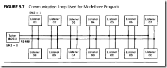
A multiprocessor configuration that demonstrates the use of mode 3 is shown in Figure 9.7. An RS 485 twisted-pair transmission line is used to form a loop that has 15d 8051 microprocessors connected to the lines so that all data on the loop is common to all serial ports. The 8051 has been programmed to be the talker, and the rest are listeners.
The purpose of the loop is to collect ten data bytes from each listener, in sequential order. All listeners initialize SM2 to I after power-up. and the talker configures all address
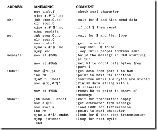
messages using a 1 in bit ten. Addressed listeners transmit ten data characters to the talker with bit ten set to 0. The talker has SM2 set to 0 so that all communications from listeners are acknowledged. Data characters from a listener to the talker are ignored by the remaining listeners. At the end of the ten data bytes, the addressed listener resets SM2 to 1. The data rate is set by timer 1 in the auto-reload mode to be 83333 baud. That portion of the talker and listener program that has to do with setting up the multiprocessor environment will be programmed.
The messages that are sent from the talker to the listeners are called "canned" because the contents of each is known when the program is written; the messages can be placed in ROM for later use. The subroutine "sendit" in the talker program can send canned messages of arbitrary length, as long as each message ends in the character$.
Message contents from the listeners to the talker are not known when the program is written. A version of sendit, "sndat," can still be used if the message is constructed in the same manner as the canned messages in the ROM of the talker program.
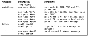
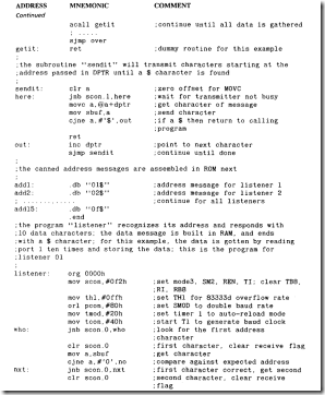
The program "Modethree " sends a canned address message to each of Fh listeners on a party-line loop using serial data mode 3. All canned messages are transmitted with bit ten set to I; all received data from the addressed listener has bit ten set to 0. SM2 is set in all listeners and reset in the talker.
COMMENT
The inclusion of the $ character in each message is useful both as a check for the end of a message and to reset a listener that somehow misses one of the three characters expected in an address. If a listener misses a character, due to noise for example, it will get to the "no" label within one or two characters. The next $ will reset the listener program back to the "who" label.
Programs that interchange data must be written to eliminate any chance of a receiving unit getting caught in a trap waiting for a predetermined number of characters. Common schemes that accomplish this goal use special "end-ot-messsqe" characters, as in the case of Mode three, or set timers to interrupt the receiving program if the data is not received within a certain period of time.
Much more elaborate protocols than those used here in this example would be used by the listeners when sending data to the talker. There is always the possibility that errors will occur due to noise or the improper operation of another listener interfering. The talker may store these errors. Error-checking bytes may be added to the data stream so that the talker can verify that the string of characters is error free.
Summary of 8015 Serial Data Communication
Four serial data communication modes for the 8051 are covered in this chapter:
Mode 0: High-speed, 8-bit shift register; one baud rate off/ 12
Mode 1: Standard 8-bit UART; variable baud rate using timer 1 overflows
Mode 2: Multiprocessor 9-bit UART: two baud rates of f/32 and f/64
Mode 3: Multiprocessor 9-bit UART: variable baud rate using timer 1over flows
Programs in this chapter use these modes and feature several standard communication techniques:
High-speed shift register data gathering
Interrupt-driven transmit and receive buffers
Sending preprogrammed, or canned, messages
Problems
I. Explain why mode 0 is not suitable for 8051 communications.
2. How much clock skew. in terms of clock period, can transmitted data using mode 0 have before data is shifted in error?
3. Repeat Problem 2 for data reception.
4. Assume you are determined to use mode 0 as a communication mode from one 8051 to another. Outline a system of hardware and software that would allow this. Hint: A "buffer" is needed.
5. Sketch the mode I no parity ASC11 serial characters U. 0. and w.
6. Many communication terminals can determine the baud rate of standard (mode 1) char· acrers by making measurements on the first few "fill" characters received. Outline a program strategy that would set the 8051 baud rate automatically based upon the first character received.
7. Character transmission can be done by using a time delay greater than the character time before moving a new byte to SBUF. Explain why character reception must use an interrupt flag if all characters are to be received.
8. ASCII characters can have even (number of ones). odd, or no parity using bit 7 as a parity bit. Write a program that checks the incoming data for odd parity and sets a flag if the parity is incorrect.
9. Write a program that converts odd parity bytes to even parity bytes (bit 7 is the parity bit).
10. An overrun is said to occur in data reception whenever a new byte of data is received before the previously received byte has been read. Discuss two methods by which overruns might be detected by the 8051 program.
11. List two reasons why stop bits arc used in asynchronous communications.
12. A framing error is said to have occurred if the stop bit is not a logic high. What mode(s) can detect a framing error?
13. Why is it necessary for the main program (see "Modeone") to set the T1 bit to begin the transmission of a string of characters using interrupt-driven routines? Name another way for the main program to initiate transmission.
14. Determine if an 8051 in mode I can communicate with an 8051 in mode 3.
15. Modify the "Modeone " program to use 4K byte buffers.
